The strange thing is DHL says they made two delivery attempts, one at 10.34 hrs and one at 10.39 hrs, then they say it was delivered at 12.20 hrs. I think I will give them a call tomorrow…
Called DHL, they told me they handed it over to PostNL. Turned out it was delivered at a pick up point nearby. Would have been nice if they had told me it was there…
GR vs BL grades
FWIW, I matched a batch of 30 SK209 BL @ 3 mA current, VGS was between 280 and 376 mV which gives source resistor values (R4/R5) between 93 and 125 Ohm for 3 mA CCS current (I DSS of the same batch was between 7,60 and 9,40 mA btw). I picked 4 JFets as current sources where I had the exact resistor values in the drawer, but I could have used the whole batch to get exact matches both for the current sources and the input pairs.
FWIW, I matched a batch of 30 SK209 BL @ 3 mA current, VGS was between 280 and 376 mV which gives source resistor values (R4/R5) between 93 and 125 Ohm for 3 mA CCS current (I DSS of the same batch was between 7,60 and 9,40 mA btw). I picked 4 JFets as current sources where I had the exact resistor values in the drawer, but I could have used the whole batch to get exact matches both for the current sources and the input pairs.
Impressive, Martin! Really cool that you did that. I have never matched anything myself. I do wonder what jig you had to construct to match those tiny parts. Care to share a pic? Impressed!
Andy
Andy
matching
You could use this to match SMD-JFets..... 😉
Greets
Dirk 😀
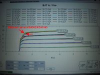
Didn't find my pics of 2SK209-matching.....
only from the KSA992/KSC1845
You could use this to match SMD-JFets..... 😉
Greets
Dirk 😀
Didn't find my pics of 2SK209-matching.....
only from the KSA992/KSC1845
Attachments
I knew you did that, Dirk. What is it that you don’t do yourself? Impressive all the way!
Can I ask where you got hold of that stuff?
Cheers,
Andy
Can I ask where you got hold of that stuff?
Cheers,
Andy
Last edited:
to andynor #2546
Hello Andreas,
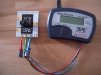
I've bought my Peak DCA75 Pro at the german parts distributor -
Security Check
Security Check
At the moment good price at 109.17 € (I have bought mine at 123,10€).
Or you can buy directly from PEAK ( they are in England)
Test Instruments | Peak Electronic Design Limited
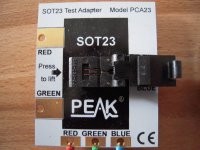
The SMD - adapter was bought from PEAK directly.
SOT23 Peak Component Adapter | Peak Electronic Design Limited
You only need a laptop - and... let's match
Greets
Dirk 😀
p.s.: The DCA75Pro can test to a maximum voltage of 12V
To test Mosfets for higher railvoltages - it is not perfectly suited
but it also works
Hello Andreas,
I've bought my Peak DCA75 Pro at the german parts distributor -
Security Check
Security Check
At the moment good price at 109.17 € (I have bought mine at 123,10€).
Or you can buy directly from PEAK ( they are in England)
Test Instruments | Peak Electronic Design Limited
The SMD - adapter was bought from PEAK directly.
SOT23 Peak Component Adapter | Peak Electronic Design Limited
You only need a laptop - and... let's match
Greets
Dirk 😀
p.s.: The DCA75Pro can test to a maximum voltage of 12V
To test Mosfets for higher railvoltages - it is not perfectly suited
but it also works
I have never matched anything myself.
High Andy,
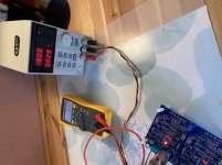
I usually match all my JFets, and matching for IDSS is pretty easy to set up, at least in principle, except that you need a special socket for the new small packages. There are plenty of references available that show the basic matching setup, my recommendation is to read the Borbely Article “JFETS: The New Frontier, Pt. 1” (should be easy to find, Zen Mod put up a link recently. I used his setup Fig. 5 for my measurements.)
I also have a DCA 75 but I am a bit disappointed in that it is not exact enough to match high GM JFETs, at least for some applications. The good news is that Wayne’s line stage does not seem to require matching, at least for GR parts, though matching certainly does not harm either. I matched my JFets at operating current because a) they are BL grade with higher currents and b) because I need to run the stage at +/- 30 Volts. This requires to control dissipation, especially in the drivers Q9/Q14. Increasing the emitter resistors resistors R7/R13 to 200 Ohms still gives 300mW dissipation for 500mW parts, which is as high as I wanted to go.
Talking of dissipation, measuring for IDSS heats up the parts. It is still ok for TO92 packages but those tiny new parts heat up quickly. This is another reason to match at operating current as that gives more stable readings.
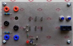
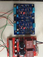
Since you asked for a picture, here is my measurment board. As you can see there is not much to see, and this is still work on progress.
In the middle of the board I have 2 x 3 sockets for different pin-outs plus something to connect clip leads for the external sockets, the bottom row is for N-channel parts, top row for P-channel. Bottom center (red LED) shows the current source for the N-channel, right now with a fixed current setting resistor, but I want to make that switchable via DIP switches. P-channel current source will follow.
In the middle of the board I have 2 x 3 sockets for different pin-outs plus something to connect clip leads for the external sockets, the bottom row is for N-channel parts, top row for P-channel. Bottom center (red LED) shows the current source for the N-channel, right now with a fixed current setting resistor, but I want to make that switchable via DIP switches. P-channel current source will follow.
Attachments
Hi, Martin - and thank you so much for that contribution! I have a spare set of WLS PCBs, so I am considering matching the next time around. Maybe for a headphone amp? Or balanced WLS?
Anyways, I messed up my first board. Something about PSU wires not meant for signal input block or along those lines... eheemmmm... so wanna get one working before spending time matching devices. I do have maaaany devices.
Anyways, in between being with family and doing housework, the last few days I managed to assemble a new PCB.
Just fired up.
Stable offset below 0mV, drift around +/- 1 mV. Current draw 28-29 per side. Current from JFETs to 10R resistors 3.1mA /31mV drop.
Looking good. But still hoping it won’t go ape during testing 🙁 Next up is the other chan, then have a look in the scope. Then do sinewaves and squares, we’ll see then. Looking good so far!
Attachments
Thanks man! It’s been an unnesscessary journey, but a learning experience for sure.
Other chan also seems OK. Measures almost completely the same. Current drops over 150R resistors means both channels send about 13mA to the LEDs. Just about as prescribed.
Other chan also seems OK. Measures almost completely the same. Current drops over 150R resistors means both channels send about 13mA to the LEDs. Just about as prescribed.
Last edited:

Aah, finally! [emoji1376][emoji1376][emoji1376]
(Mine is doing fine again too, btw)
Good to hear! What caused the hum and noise?
to andynor and my leftear
Hello WLS-builders,
I hope to see success in the near future! Don't go too fast and think about each step you are doing....
Waynes Line Stage is such a nice preamp. 😉
I hope you will listen to a fantastic 'sound machine' soon....
Cheers
Dirk 😀
p.s.: my WLS makes absolutely no audible noise
Hello WLS-builders,
I hope to see success in the near future! Don't go too fast and think about each step you are doing....
Waynes Line Stage is such a nice preamp. 😉
I hope you will listen to a fantastic 'sound machine' soon....
Cheers
Dirk 😀
p.s.: my WLS makes absolutely no audible noise
Good to hear! What caused the hum and noise?
I believe it was the gardener [emoji23]
(No, seriously, i don’t know. It hummed, I tore it apart, put it back together and bam it is good—sloppy work or something… here, aside some rfi-pickup/line-noise from the aca or the furutec-HPA/DAC, all is quiet too.)
Last edited:
Hello WLS-builders,
I hope to see success in the near future! Don't go too fast and think about each step you are doing....
Waynes Line Stage is such a nice preamp. 😉
I hope you will listen to a fantastic 'sound machine' soon....
Cheers
Dirk 😀
p.s.: my WLS makes absolutely no audible noise
Thank you, Dirk!
Now that I found the gardener (=me) was the murderer, I am rebuilding it… very carefully this time, trying to avoid mishaps and other „fat bowls“ [emoji56]
Which is very entertaining and inspirational!
Longtime lurker - finally done with soldering
Longtime lurker with more hope than electronic knowledge de-cloaking here. This thread was a great help, and after a brief false start with no LED lit on one channel, a cold joint was found on one of the tiny three legged critters - all was well after a quick dab of flux and extra solder. Offset adjusted great to zero with a bit of drift to 0.001. Into enclosure to replace my B1 next (didn't really warm to that) as soon as I can get either new 5 or 8 pole XLRs for the remote PSU, depending on whether I decide one or two of the pictured Sjostrom/s I have are needed. Thanks all and particularly to the author of the Board.
T
Attachments
- Home
- Amplifiers
- Pass Labs
- Wayne's BA 2018 linestage