I'd like to do my own version of the capacitance multiplier, similar to the MrEvil / PMI one but using BJTs + MOSFET pass transistors. When I return to that I'll do some show and tell here as well.
Looking forward to that Jason.
Quan
It's ALIVE!
Hi Guys,
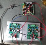
It is alive and well! My parts finally arrived so I was able to complete it. I brought it up on the Variac through a light bulb limiter and was able to set the VAS to 160mV across R14 and then set the bias to 160mA through an ammeter on the rails. Once everything was set and looking good I hooked up the SMPS to make sure everything would still be happy. All looked good so I hooked up some test speakers and played some music through it. Once satisfied I hooked it up to my main A/B setup so I could compare it to Pete's VSSA. Absolutely identical to the ear. I had two other people listen and neither could hear any difference. I'd say the SMPS is a keeper. Oh, did I mention how killer the VSSA sounds. 😀
A pic attached, Don't mind the rats nest. That will get tidied up later. Right now I'm enjoying listening to it. 😀
Blessings, Terry
Hi Guys,
It is alive and well! My parts finally arrived so I was able to complete it. I brought it up on the Variac through a light bulb limiter and was able to set the VAS to 160mV across R14 and then set the bias to 160mA through an ammeter on the rails. Once everything was set and looking good I hooked up the SMPS to make sure everything would still be happy. All looked good so I hooked up some test speakers and played some music through it. Once satisfied I hooked it up to my main A/B setup so I could compare it to Pete's VSSA. Absolutely identical to the ear. I had two other people listen and neither could hear any difference. I'd say the SMPS is a keeper. Oh, did I mention how killer the VSSA sounds. 😀
A pic attached, Don't mind the rats nest. That will get tidied up later. Right now I'm enjoying listening to it. 😀
Blessings, Terry
Attachments
Sweet work Terry! You are the first outside of myself to get a set up and running. Hopefully we see some of the others get builds running too shortly.
Hehehe, are you suggesting designing it and getting the boards first was an advantage? To be totally fair you get your builds up and running pretty fast my friend.
How did you find set up? They are pretty straight forward to calibrate in my opinion.
How did you find set up? They are pretty straight forward to calibrate in my opinion.
Last edited:
Setting the VAS is the most time consuming. I used three multimeters. One set as an ammeter on the rail, another across R14 and the other on the output. I used two screwdrivers and watched the two voltmeters. It felt like driving a slip-turn. 🙂
I just turned down the bias to 120mA. The heatsink I have the two boards mounted got too hot with it at 160mA. I can't really hear any difference with it set cooler. I'm going to let it play most of the day today so the caps can set in. Another keeper. The Ovation nx is next. Another CFA. 😉
I just turned down the bias to 120mA. The heatsink I have the two boards mounted got too hot with it at 160mA. I can't really hear any difference with it set cooler. I'm going to let it play most of the day today so the caps can set in. Another keeper. The Ovation nx is next. Another CFA. 😉
I notice in your picture you elected not to use the ground for speaker return. Just force of habit from other builds or do you find advantage in returning directly to the PSU?
It's hard to see in the picture. You provided two places to attach ground. I used the one between the two rail lugs. If you look closely you can see a green wire attaching there. Those green wires go to a star ground out of the picture where the speaker grounds attach as well as the ground from the SMPS. I just use a group of spade connectors as a star for my testing. Once in a case they will all return to a bolt with a bridge ground loop breaker to the earth ground.
My intent was one spade for the PSU ground and one for the speaker return. Anyhow, it doesn't actually matter, it was just an observation.
First steps towards an enhanced VSSA
Folks,
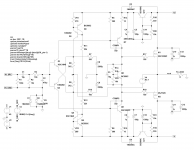
After some playing about with the simulations to improve its rejection of power supply flotsam I propose this: Use a low current CM to feed the CCS and VAS.
There seems to be little real advantage to a high current CM to feed the whole thing since it is really the VAS that is the sensitive bit. This would only require a couple of small signal devices to be located on board and a few more passives. The PSRR at 120Hz improves by more than -30dB, seems a worthwhile addition. Thoughts?
Folks,
After some playing about with the simulations to improve its rejection of power supply flotsam I propose this: Use a low current CM to feed the CCS and VAS.
There seems to be little real advantage to a high current CM to feed the whole thing since it is really the VAS that is the sensitive bit. This would only require a couple of small signal devices to be located on board and a few more passives. The PSRR at 120Hz improves by more than -30dB, seems a worthwhile addition. Thoughts?
Attachments
Jason,
Starting to stuff boards with components I have on hand, and will order remainder. I'm a little confused by your labeling of the trimmers. On the board the resistance is shown as 220 for VR1 and 3. The BOM for those is 500R. So I interpret that as using a 500R trimmer with an eventual target setting of around 220R. For VR2, the BOM shows a 5k trimmer, but the schematic value for that resistor is 10K. Do we want a 10k trimmer with a target value around 5K? Or simply a 5k trimmer.
Sheldon
Sheldon,
The silk on the boards should read 500R for VR1 and VR3 and 5K for VR2, I'm not able to verify at the moment what is printed on the silk, it should match the image in the first post of this thread. Trimmers VR1 and VR3 are to be pre-set to 270 ohm and VR2 is set for maximum resistance. My apologies if there are any descrepancies, I will check my published documents later when I'm at my computer and reference post numbers to verify which document you are referencing.
Edit: it looks like the post with the BOM, schematic and drill template did not make it here when the thread was split. Have a peek back in PMI's thread to see if it is there. I'll try to fix that or repost it later when I have more capability at home.
Last edited:
Sheldon,
The silk on the boards should read 500R for VR1 and VR3 and 5K for VR2, I'm not able to verify at the moment what is printed on the silk, it should match the image in the first post of this thread. Trimmers VR1 and VR3 are to be pre-set to 270 ohm and VR2 is set for maximum resistance. My apologies if there are any descrepancies, I will check my published documents later when I'm at my computer and reference post numbers to verify which document you are referencing.
Thanks Jason. Seems the only confusion is on the as built schematic. That part is indicated as VR2-5K and underneath that label is also a 10k label. I'll ignore the 10k.
Thanks Jason. Seems the only confusion is on the as built schematic. That part is indicated as VR2-5K and underneath that label is also a 10k label. I'll ignore the 10k.
Yes, that must have been a vestige from simulation (the Cordell models for the output MOSFETs threshold voltage is lower than reality). My apologies for any confusion, the silk is accurate for the values.
Terry,
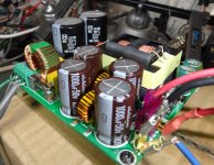
What are the specs of your SMPS and how much is the capacitance of the output smooting caps?
What are the specs of your SMPS and how much is the capacitance of the output smooting caps?
Hi guys, couple of questions. I see there are holes under R21? Significance?. Also with the Miller cap 22pF -would sli deviation be ok ie 18pf?.
Quan
Quan
There are four holes that are vias between the layers, two under R21, one under R20 and one near C5. They don't carry much current so can be left as-is, or filled with a little solder (my preferred choice).
As for compensation, there's some latitude there. I'd suggest 18pF should be fine. You could also go a little higher too, up to perhaps 47pF.
As for compensation, there's some latitude there. I'd suggest 18pF should be fine. You could also go a little higher too, up to perhaps 47pF.
There are four holes that are vias between the layers, two under R21, one under R20 and one near C5. They don't carry much current so can be left as-is, or filled with a little solder (my preferred choice).
As for compensation, there's some latitude there. I'd suggest 18pF should be fine. You could also go a little higher too, up to perhaps 47pF.
Thanks Jason.
- Status
- Not open for further replies.
- Home
- Amplifiers
- Solid State
- VSSA Through-Hole Version by Jason