Yes, these are room temperature matches and that may play a factor in what we get. The ones I sent you are near exact matches on the tracer at the same settings, again at room temperature.
I may be able to do a static test to see what I get from that. If I can, I'll shot for the same 14mA benchmark after equalizing the temperature.
I may be able to do a static test to see what I get from that. If I can, I'll shot for the same 14mA benchmark after equalizing the temperature.
I have been trying to mail as many as possible without customs forms. It just makes it less reliable to go through Customs.Mine have not arrived yet...
I guess the time at customs is not always the same...
Fab

Two earlier bigger packages mailed at a higher cost, and with more forms, are still unaccounted for... one to Europe, and one to India.
Unaccounted for in the sense,that the recipient never got it?
Did you ask him to check with his head-post office?or the regional one?There is this weird rule that,any package,coming to India from overseas,if it passes through the postal system(not a private courier) and is above INR2000 or about ~32USD,is liable to be seized and taxed as per their whims.Or atleast thats what I understood.
Did you ask him to check with his head-post office?or the regional one?There is this weird rule that,any package,coming to India from overseas,if it passes through the postal system(not a private courier) and is above INR2000 or about ~32USD,is liable to be seized and taxed as per their whims.Or atleast thats what I understood.
Unaccounted for in the sense,that the recipient never got it?
Did you ask him to check with his head-post office?or the regional one?There is this weird rule that,any package,coming to India from overseas,if it passes through the postal system(not a private courier) and is above INR2000 or about ~32USD,is liable to be seized and taxed as per their whims.Or atleast thats what I understood.
Dear Pete,
Please let me know the date and other details of your dispatch, and I shall contact the local Post office about it.
gannaji
PM sent.Dear Pete,
Please let me know the date and other details of your dispatch, and I shall contact the local Post office about it.
gannaji
Yes, two packages sent about 2 months ago never arrived. One to India, and one to Europe.Unaccounted for in the sense,that the recipient never got it?
Hi Pete,
payment made for
1 set of VSSA boards, 5 sets of BC546c/556c and 5 sets of ksa1381/ksc 3503
thanks
kp93300
payment made for
1 set of VSSA boards, 5 sets of BC546c/556c and 5 sets of ksa1381/ksc 3503
thanks
kp93300
VAS transistors
From now on, I can only send one set of the KSC3503-E/KSA1381-E with the boards. (Multiple sets before today will be shipped as promised.)
The point of getting these was to make sure they were available to build the VSSA boards with the parts Lazy Cat specified, not to sell them in quantity.
From now on, I can only send one set of the KSC3503-E/KSA1381-E with the boards. (Multiple sets before today will be shipped as promised.)
The point of getting these was to make sure they were available to build the VSSA boards with the parts Lazy Cat specified, not to sell them in quantity.
Hello PMI,
Just listing payment notice here as others have...(2 PCB's & 1 set 3503/1381)
Thanks
Just listing payment notice here as others have...(2 PCB's & 1 set 3503/1381)
Thanks
Hi PMI,
Following a quick scan of the whole thread, I cannot find :
a) What, other than the PCBs, is available. It seems that the OPT. devices could be available? Heatsinks?
b) Net costs...[obviously shipping Paypal charges to be added.]
Is it possible to include this info in the 1st post?
Many thanks
Following a quick scan of the whole thread, I cannot find :
a) What, other than the PCBs, is available. It seems that the OPT. devices could be available? Heatsinks?
b) Net costs...[obviously shipping Paypal charges to be added.]
Is it possible to include this info in the 1st post?
Many thanks
Thanks for the comment and the suggestions. I will try to add more information, and other suggestions are welcome, but there is not always enough time to do so.Hi PMI,
Following a quick scan of the whole thread, I cannot find :
a) What, other than the PCBs, is available. It seems that the OPT. devices could be available? Heatsinks?
b) Net costs...[obviously shipping Paypal charges to be added.]
Is it possible to include this info in the 1st post?
Many thanks
a)
I tried to have some of the parts which are harder to get available with the boards, so people should not feel limited by component availability, but there are substitutes for every part.
Jfets used in the CCS: So far I have been shipping a set of J112 N-channel jfets with every board at no extra charge. In the US, these are easily available, and cost very little in quantity~11 cents/100. At the same time, they seem to be hard to obtain for some people. Other N-channel jfets can be used if they have the same pinout and TO-92 package, assuming the resistor values in the CCS circuit are adjusted for the selected jfet type.
Input transistors: BC550C/560C (up to 45V supply) are available and should be used at power supply voltages up to +/-45V. BC546C/556C (up to 65V supply) can be hard to find, because BC556C is obsolete. I have enough of the BC546C/BC556C to send to anyone who want to use them, but please note that if you intend to do a build close to Lazy Cat's original directions, you should use the BC550C/560C.
VAS transistors: Lazy Cat's original VSSA modules used KSA1381-E/KSC3503-E in the VAS. KSC3503-E is obsolete. I have enough of these to include with all the boards - for now. There are also substitutes, discussed in this thread and in the PeeCeeBee thread.
VAS Heatsinks: A number of small U-shaped or H-shaped heatsinks will fit. The heatsinks shown in pics of my board are a popular and low-cost type sold online, about 35 cents each, with free shipping. From a seller called "Goldpart" on ebay, and several other sources online. I will cover this in a separate post.
Output Devices: Listed in the BOM. Renesas 2SK1058/2SJ162 or Semelab ALF08N/08P16V. Availability varies depending on where you are located. I have been ordering the Renesas parts from Tayda Electronics online, for about $5/each, with nominal shipping. Semelab parts are usually listed as UK stock, so may be easy to get in Europe, and hard to get in the US (~$7 + shipping and handling).
b)
With the exception of the last few people who signed up, everyone should have received a message with board and component costs including shipping an paypal. The International shipping costs will probably go up, because the US Post Office is starting to force anything other than paper to be shipped as a package. Here is what was sent out:
International First Class Mail, regular postage:
Set of two boards, total $25.50
Each additional set, add $23.--
US Domestic First Class Mail:
Set of two boards, total $23.80
Each additional set, add $21.50
Canada: Add 50 cents to US prices for extra postage
Optional Transistors:
One set KSA1381-E/KSC3503-E, $2
One set BC546C/BC556C, $1
(one set = 2 pair = 4 transistors)
edit:
I probably can't get all this into the first post, but I have added a link there.
Last edited:
Thank you a lot for clarifying the position. I will shortly PM you with an order....need to scratch my head first!
Brian
Brian
VAS Heatsinks
When reading heatsink ratings, the "Thermal Resistance" figure shows the expected increase over ambient temperature for each watt power dissipation. In general, lower figures are better.
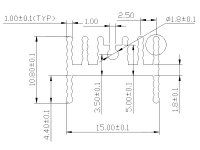
The heatsinks shown in pictures of the VSSA rev. C board are small extrusion-type TO-220/TO-126 heatsinks, with tapped holes for M3 screws. See first pic below for dimensions. This heatsink is a popular type sold on ebay and elsewhere online. These were purchased from an ebay seller called "Goldpart", and cost about $0.35 each, with free shipping. The seller ships very quickly, even from China.
Common U-shaped aluminum heatsinks can also be used, up to a 15x13 mm footprint. Dimensions are usually listed with the thermal specs. Example:
From Mouser, Aavid Thermalloy 577202B00000G
Heatsink temperature can be estimated from the power supply voltage and VAS bias current.
Example, for the Aavid Thermalloy heatsink above:
Supply voltage: +/-36V
VAS bias current: 14 mA
Thermal rating: 25C/watt
Temp. Rise above ambient: 36V * 0.014A * 25C/watt ~ 12.5C
This is an estimate, expect figure to be about 5C higher. Proximity to the main heatsink may increase the temperature another 2~4 degrees, and so will internal chassis temperature.
The KSA1381/KSC3503 transistors have an all-plastic body, and a small amount of thermal grease should be used for best contact with the heatsink. The heatsinks from Goldpart are tapped for M3 screws, length about 8~10 mm. Example: M3x8 + flat washer (M3x10 + lock washer optional). The
Aavid Thermalloy heatsinks are not tapped, so those require a nut or similar fastener. Example: Aavid Thermalloy p/n 577202B00000G + M3x10 + lock washer + flat washer + M3 nut. Typical mounting hardware is shown in the second pic below.
The TO-126 transistors should be mounted on the heatsinks before they are soldered to the board. Usually, it will be best to assemble the VAS transistors after all the smaller parts, and before the taller electrolytic capacitors.
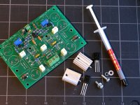
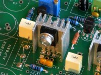
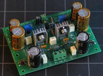
The second pic below shows what the board should look like before assembling the heatsinks and transistors. The third pic is a close-up of the soldered heatsink and transistor. The last picture is an almost complete board, after the tallest caps are soldered.
A typical assembly sequence will be as follows:
When reading heatsink ratings, the "Thermal Resistance" figure shows the expected increase over ambient temperature for each watt power dissipation. In general, lower figures are better.
The heatsinks shown in pictures of the VSSA rev. C board are small extrusion-type TO-220/TO-126 heatsinks, with tapped holes for M3 screws. See first pic below for dimensions. This heatsink is a popular type sold on ebay and elsewhere online. These were purchased from an ebay seller called "Goldpart", and cost about $0.35 each, with free shipping. The seller ships very quickly, even from China.
Common U-shaped aluminum heatsinks can also be used, up to a 15x13 mm footprint. Dimensions are usually listed with the thermal specs. Example:
From Mouser, Aavid Thermalloy 577202B00000G
Heatsink temperature can be estimated from the power supply voltage and VAS bias current.
Example, for the Aavid Thermalloy heatsink above:
Supply voltage: +/-36V
VAS bias current: 14 mA
Thermal rating: 25C/watt
Temp. Rise above ambient: 36V * 0.014A * 25C/watt ~ 12.5C
This is an estimate, expect figure to be about 5C higher. Proximity to the main heatsink may increase the temperature another 2~4 degrees, and so will internal chassis temperature.
The KSA1381/KSC3503 transistors have an all-plastic body, and a small amount of thermal grease should be used for best contact with the heatsink. The heatsinks from Goldpart are tapped for M3 screws, length about 8~10 mm. Example: M3x8 + flat washer (M3x10 + lock washer optional). The
Aavid Thermalloy heatsinks are not tapped, so those require a nut or similar fastener. Example: Aavid Thermalloy p/n 577202B00000G + M3x10 + lock washer + flat washer + M3 nut. Typical mounting hardware is shown in the second pic below.
The TO-126 transistors should be mounted on the heatsinks before they are soldered to the board. Usually, it will be best to assemble the VAS transistors after all the smaller parts, and before the taller electrolytic capacitors.
The second pic below shows what the board should look like before assembling the heatsinks and transistors. The third pic is a close-up of the soldered heatsink and transistor. The last picture is an almost complete board, after the tallest caps are soldered.
A typical assembly sequence will be as follows:
- Apply small dab (2-3 mm in diameter) of thermal grease to heatsink
- Attach VAS transistor using M3 mounting screw, finger tight
- Insert into board and solder transistor leads w. heatsink in place
- Loosen mounting screw
- Make sure heatsink is seated against board, if not, reflow transistor leads
- Re-tighten mounting screw
- Solder heatsink retaining pin, if the heatsink has one
Attachments
.and thank you for the post above.
I intend building one stero amp on your boards and another as a mixture of perf board and spiders web.......a method I have used before. I am already building the LC version and will soon be ready to use it. To compare these three set should be interesting...esp as I intend using one dual power supply, so any differences can only be down to construction, parts and layout.
I intend building one stero amp on your boards and another as a mixture of perf board and spiders web.......a method I have used before. I am already building the LC version and will soon be ready to use it. To compare these three set should be interesting...esp as I intend using one dual power supply, so any differences can only be down to construction, parts and layout.
You are welcome.Thank you a lot for clarifying the position. I will shortly PM you with an order....need to scratch my head first!
Brian
I don't want to limit other people to parts "specified" by me, that would sort-of defeat the whole diy concept. So, that means having options, and that makes it seem more complicated than it really is.
What attracted me to Lazy Cat's design in the first place, was that the performance was excellent with relatively few parts. In other words, it sounded great, it did not just look good in simulations, and it was easy to assemble.
I would also note that Shaan got very good results with an even simpler set of parts, and lower supply voltage, and that his results were repeated by several other people. His schematic is in the first post of the PeeCeeBee Thread, along with lots of other useful information on the first few pages.
Be careful of the VAS bias current. Most people building the through-hole versions seem to be biasing on the high side, which may not always be a good thing. The VAS current will rise in relationship to the temperature and the positive temp coefficient of the VAS transistors (tested).... To compare these three set should be interesting...esp as I intend using one dual power supply, so any differences can only be down to construction, parts and layout.
Jason's tests with a curve tracer indicate a lower knee in the gain curve than what one might expect based on the datasheets. Post 218 and 219.
Some people may not notice much, but if you are going to be doing a-b-comparisons, it might make a difference where the VAS is biased.
.....Some people may not notice much, but if you are going to be doing a-b-comparisons, it might make a difference where the VAS is biased.
 .....
..... .....
..... ......
Agree, and praise to you for taking time/concern to explain.
- Home
- Amplifiers
- Solid State
- VSSA Through-Hole-PCB build thread