According to the schematic on the first post denoiser is used without the jumper installed. That explains the bouncing (over- and undershoot of the denoiser). It also explains why you had only -15.5V earlier. Denoiser was probably oscillating.
This is correct it had issues with the de-noise engaged. There was still an issue, but the correct voltage was there. When I put a scope on it there was still and oscillation though not as bad. Lest it get lost in the thread the issue was, mainly with a non BOM chip, but morestsble values were determined and I think the BOM and schematic were updated.
I am planning on using this PSU for my Pearl 2 build.
Due to limited space my plan was to go the wallwart path to try to keep noise from being picked up by the Pearl.
I don't know Sutherland gets by with them and was going to base my plan of attack on there 20/20 version.
Anybody try something like this before?
Due to limited space my plan was to go the wallwart path to try to keep noise from being picked up by the Pearl.
I don't know Sutherland gets by with them and was going to base my plan of attack on there 20/20 version.
Anybody try something like this before?
The pearl 2 needs +/- 27 to 30v DC on its inputs, and it has onboard regulators, so you can have a simple raw supply.
If you bypass the board regulators you’ll need regulated +/- 24vdc.
You could use VRDN board as a raw supply, basically rectifiers and filter caps only.
If you bypass the board regulators you’ll need regulated +/- 24vdc.
You could use VRDN board as a raw supply, basically rectifiers and filter caps only.
My bad, I had the boards and thought it needed 18 volts, must have gotten it mixed up with Waynes line stage.
Oh well, looked good on paper.
Oh well, looked good on paper.
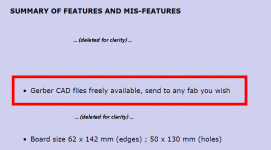
PCB Prototype & PCB Fabrication Manufacturer - JLCPCB [emoji83]😉
(We‘re supposed to care ourselves for the procurement of the boards—easily done with the files mark gave us!)
(We‘re supposed to care ourselves for the procurement of the boards—easily done with the files mark gave us!)
What is the tool for forming resistor leads for the upright orientation as seen on this board.?
Or do you just do it manually?
Or do you just do it manually?
Pretty easy to do it manually. You can also put a small stick (a popsicle stick, eg) along the resistor and bend it around that. But I just did it without it.
Some builders have enjoyed experimenting with their nee-nee-needley-est needle nose pliers. By studiously making test-bends upon ten or twenty expendable, disposable resistors, these folks have discovered just the perfect distance-from-jaw-tip to grip the wire, so they get zzzzzactly the bend radius they seek.
Not all builders, of course.
Not all builders, of course.
VRDN Measuements
Since no one else has posted any measurements of the VRDN, I figured I would have a go at it. I measured both rails set at 12 volts with 180 ohm resistors on the outputs for a 66mA load. I did parallel the resistors on the positive rail for a 132mA load and it raise the noise level about 2dB is all, statistically insignificant.
The 0dB level is set to 9,238.9 mVpeak or 12.5dBu.
Positive Rail

Negative Rail

Since no one else has posted any measurements of the VRDN, I figured I would have a go at it. I measured both rails set at 12 volts with 180 ohm resistors on the outputs for a 66mA load. I did parallel the resistors on the positive rail for a 132mA load and it raise the noise level about 2dB is all, statistically insignificant.
The 0dB level is set to 9,238.9 mVpeak or 12.5dBu.
Positive Rail
Negative Rail
I'll be very interested to see yours to see if they match somewhat. I think I'm doing the measurement right, but who knows, LOL.
Pretty sure the little bit of 60Hz was a parasitic from the cables, you notice it isn't in the negative rail.
I saw that, but I'm not convinced it's not the same thing, not recorded properly. Just looking at the form, I'm thinking it is the same regardless of where it is recorded.
Are these classed as good results then? And ...being the novice....I read that the output impedance to be as important as the noise if not more so. Do we know the impedance of this psu?
Thanks
Thanks
Seems to match my findings with the denoiser.
If the denoiser is working then output impedance should be low.
If the denoiser is working then output impedance should be low.
- Home
- Amplifiers
- Power Supplies
- VRDN: bipolar regulator PCB for line level ckts: ±11V to ±20V @ 1.5A with "De-Noiser"