The reality can be strange indeed. I have encountered IC's in devices that developed an internal fault which made the device useless. These IC's were replaced only to discover that they themselves were not revised and developed the same fault again 🙂 Even after years the same fault became known as a repeatedly ocurring series issue...
I went back and took another look to make sure it was stable through the adjustment range and mine looks good from the lowest to highest value of VR1 and VR2. All I did was change C14 & C16 to 33nF.
As long as mine is stable, I'm inclined to leave it alone....
JT
As long as mine is stable, I'm inclined to leave it alone....
JT
I’m very thankful to everyone who gives their electronic knowledge willingly on this site!
Great work Mr. Johnson!!
Great work Mr. Johnson!!
I had dug through my parts drawer from about 10 years ago to kit up the builds. I found ST 337's and Fairchild and Motorola 317's. I assume the 317's are OK since both companies are now part of ON Semiconductor. But I haven't seen anything about the ST 337's.
Any suggestions?
Any suggestions?
When you get the bare PCB, mechanically assemble both heatsinks + TO220 regulator chips + thermal pads + shoulder bushings + nut + bolt + lockwasher. Now insert the TO220 + heatsink assemblies into the PCB -- you'll need to bend the leads into a slight jog for the smoothest fit.
Now ask yourself: once these things are soldered into place (a total of ten solder joints), is there any way in H.E.double.toothpicks that I could possibly unsolder and replace the TO220 regulators?
I predict your answer will be: that looks extremely difficult. Extremely.
So: if you know, in advance, that you cannot possibly replace a regulator after you solder it in, does that suggest any particular course of action?
And that my friend says it all as to replacing my TI with the ON. I have two more boards and I will use ON for those, but since it's working fine, I'm not pulling nothing. I already abused some pads with swapping Rs and Cs. It's running, it's stable it's a wrap. 😎
When you get the bare PCB, mechanically assemble both heatsinks + TO220 regulator chips + thermal pads + shoulder bushings + nut + bolt + lockwasher. Now insert the TO220 + heatsink assemblies into the PCB -- you'll need to bend the leads into a slight jog for the smoothest fit.
Now ask yourself: once these things are soldered into place (a total of ten solder joints), is there any way in H.E.double.toothpicks that I could possibly unsolder and replace the TO220 regulators?
I predict your answer will be: that looks extremely difficult. Extremely.
So: if you know, in advance, that you cannot possibly replace a regulator after you solder it in, does that suggest any particular course of action?
Anticipating your response, I have already ordered the ON parts. I may use one board for experiments after getting a couple to work.
You could populate just the negative side first. Test and determine if all is fine. It would make then populating the Positive side more difficult but not impossible. Or even temporarily installing the 337 without the heatsink. Easy to replace if needed or to pull out and then install the heatsink if it works. Mark and Elvee have done all the hard work on the oscillations. Implementing the fixes are much more easy.
Thanks for researching the subject in such detail. Your A2 values coincide much more closely with my own tests, in particular the 0Ω value for R13/R14 (a finite value is appropriate for the dienoiser and nonoiser, not the original denoiser), and the 0Ω for R22.I've been doing a lot of experiments with the two almost-identical VRDN PCBs, .....
Code:ID Rev.A Rev.A2 ------------------------ R13 15R ZEROHM C15 6.8N 10N R21 0R47 0R33 R14 15R ZEROHM C16 6.8N 22N R22 0R47 ZEROHM
This sometimes happens when IC's are used off-piste, which is the case here: we are not supposed to add loop gain to a servoed system, even in a controlled manner.... but of course most of the "clever" applications circuits provided initially by National Semi also ventured off-piste, and sometimes were not very reliable.This is the first time I've personally encountered a circuit where vendor-1's implementation of StandardChipXYZ worked well, while vendor-2's implementation of StandardChipXYZ failed badly. It's a surprise and an embarrassment: the De-Noiser is a relatively simple concept, yet it contains hidden pitfalls. I'm cautiously optimistic that this revision sidesteps the oscillation pitfall.
Transistors are much more prone to these problems: as many DIYers have discovered, replacing old, RCA 2N3055 in vintage amplifiers with recently manufactured ones results in oscillation, because the Ft is 5X higher.
Anyway, the 337 has always been temperamental, even in the completely legit, datasheet-compliant applications
IIRC, my own tests with the 337 were made with a ST, thus I don't expect any problem thereI had dug through my parts drawer from about 10 years ago to kit up the builds. I found ST 337's and Fairchild and Motorola 317's. I assume the 317's are OK since both companies are now part of ON Semiconductor. But I haven't seen anything about the ST 337's.
Any suggestions?
Board Order Help
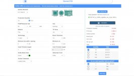
Does this look correct?
When you get the bare PCB, mechanically assemble both heatsinks + TO220 regulator chips + thermal pads + shoulder bushings + nut + bolt + lockwasher. Now insert the TO220 + heatsink assemblies into the PCB -- you'll need to bend the leads into a slight jog for the smoothest fit.
Now ask yourself: once these things are soldered into place (a total of ten solder joints), is there any way in H.E.double.toothpicks that I could possibly unsolder and replace the TO220 regulators?
I predict your answer will be: that looks extremely difficult. Extremely.
So: if you know, in advance, that you cannot possibly replace a regulator after you solder it in, does that suggest any particular course of action?
Does this look correct?
Attachments
... Found in post #1 at the top of this thread ....
SUMMARY OF FEATURES AND MIS-FEATURES
- De-Noiser circuit with jumper enable/disable
- Diodes on PCB
- Transformer Snubbers on PCB
- Big capacitors on PCB allowing true 1.5A output
- No bleeder resistors on PCB
- Voltage regulator ICs mounted on heatsinks for true 1.5A output
- Heatsink thermal resistance is 8.6 deg C per watt
- This is a four layer PCB, three of which are ground planes
- Gerber CAD files freely available, send to any fab you wish
- No "pilot light" LEDs on DC outputs
- Can use with either dual secondary trafo or AC-to-AC wall wart
- No SMD components; 100% thru-hole
- PCB unique identifier is TZPTR7 ; suffix -A means "revision A"
- PCB mounting holes compatible with Modushop chassis baseplate
- Board size 62 x 142 mm (edges) ; 50 x 130 mm (holes)
Does this look correct?
Mark’s thoroughful comments/manual says:
„This is a four layer PCB, three of which are ground planes“
On your screenshot, I read „single layer“...
not sure what to think of it. When I got my PCBs made, I just pulled the zip-file and ordered it as it came out (@jlcpcb, though)
(I see that Mark chimed in already—an hour ago! Time flies!)
Last edited:
That is what I did
I upped the zip file.
But not all the options were available, different pcb maker.
I can't get in to jlcpcb, everytime I try I get captcha error, any browser, old or new account. I emailed them and I was told IT was working on it.
I just wanted to know if what I posted was correct.
jlcpcb added a $30.00 engineering fee.
So I don't know what to do.
Merry Christmas.
Concerning jlcpcb, I'd advice to be patient a little bit, and just try again.
(I just did so and almost clicked the order-now- button: it is working for me...)
I‘m not sure if my observation was correct but I had the impression that prices for "gadgets" (blue instead of standard green in my case) dropped when I went back and repeated the whole order-process (inclusive file-upload) shortly after my first attempt, so it could be interesting for a fancy build (all pcbs blue/black/red etc)
If it works this time, you could do as many others and order a few more, to resell among other builders here. Thus, you split the engineering- and shipping-costs...
Last edited:
6.8 nF ---> 22 nF is not a gigantic change; just 10dB . It may suggest that your VRDN was just barely over the line and into "you must oscillate" territory just a wee bit. Very pleased to hear that it's now doing what you want it to do. 33nF would probably be safer still but why fix it some more if it ain't broke no longer.
Maybe this will provoke a prolonged "okay buy WHY??!?" discussion since some but not all boards oscillated.
Could be that the 6.8nF caps had long legs...
https://www.seeedstudio.com/fusion.html
I found Fusion PCB & PCB Assembly & Flexible PCB - Seeed Studio
Thank you.
Concerning jlcpcb, I'd advice to be patient a little bit, and just try again.
(I just did so and almost clicked the order-now- button: it is working for me...)
I‘m not sure if my observation was correct but I had the impression that prices for "gadgets" (blue instead of standard green in my case) dropped when I went back and repeated the whole order-process (inclusive file-upload) shortly after my first attempt, so it could be interesting for a fancy build (all pcbs blue/black/red etc)
If it works this time, you could do as many others and order a few more, to resell among other builders here. Thus, you split the engineering- and shipping-costs...
I found Fusion PCB & PCB Assembly & Flexible PCB - Seeed Studio
Thank you.
Could be that the 6.8nF caps had long legs...
No Boky, the leads were very short, body sitting on PCB.
I've created a Mouser BOM here that can be used for one-click purchase of everything needed to stuff the board. I just used the spreadsheet in the original post. Current cost is about $30 plus shipping.
Is there any reason to build the regulators using the mods that Mark made in post #198 if On semiconductor regulators are used? Does the original circuit as designed by Mark have any performance advantage over the modified circuit made to stabilize the the circuit using the TI chips?
- Home
- Amplifiers
- Power Supplies
- VRDN: bipolar regulator PCB for line level ckts: ±11V to ±20V @ 1.5A with "De-Noiser"