It is clearly stated as having a range of 11V to 20V.
Of course you could use the PCB as rectifier/passive filter/ LM regulator only and omit the de-noiser , to have an output voltage outside the 11-20V window.
Of course you could use the PCB as rectifier/passive filter/ LM regulator only and omit the de-noiser , to have an output voltage outside the 11-20V window.
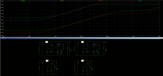
VRDN Measurements
I figured a lot of people would like to see the difference with and without the denoiser. I seriously doubt you would be able to hear much difference, but the denoiser does improve everything.
Negative Rail with DeNoiser

Negative Rail without DeNoiser

Positive Rail With DeNoiser

Positive Rail without DeNoiser

I figured a lot of people would like to see the difference with and without the denoiser. I seriously doubt you would be able to hear much difference, but the denoiser does improve everything.
Negative Rail with DeNoiser
Negative Rail without DeNoiser
Positive Rail With DeNoiser
Positive Rail without DeNoiser
Totally depends on the situation, sometimes it will, other times no.
There’s no hard and fast rule as to when/why this applies, so experimentation and trial & error is in order.
There’s no hard and fast rule as to when/why this applies, so experimentation and trial & error is in order.
I'm lazy, I'd have to pull the top off the power supply I'm using it in, LOL. Sounds good enough.
Now seeing the before/after denoiser I don't think the denoiser is adding its max performance to both rails. The denoiser should reduce the ripple and also the noisefloor at the same time by around -30dB to -35dB (vs Cadj versions). A LM3x7 +denoiser noisefloor should be around the -140dB mark, at least that is what I constantly got in my testing.
Attachments
My boards arrived so I can finally start stuffing them🙂! But before I proceed, I would like to confirm if it is possible to use a dual secondary transformer to power two boards using the "wall-wart" method? The idea is to have a separate VRDN for my volume control and one for the Wayne BA line stage, ideally using one transformer with multiple secondaries.
A LM3x7 +denoiser noisefloor should be around the -140dB mark, at least that is what I constantly got in my testing.
This numbers are incorrect. Using calibrated LNA for the measurement returns different results. Denoiser is not capable of achieving -140 dBV noise floor. I’ve measured 7 nV/rtHz noise density or 1 uV total noise, which is -120 dBV.
Dienoiser variant has 1 nV/rtHz, what gives about 0.15 uV noise and still not -140 dBV.
My 0dB is at 1.3Vrms, all LM3x7 + denoiser have the noisefloor at -140dB in my measurements. LM3x7+dienoiser is at -160dB.
-140dB from 1.3V is 0.13uV.
Since RickRay has a Focusrite Solo 3rd gen his 0dB is 8dB higher than mine. So he should see it at around -148dB on his ARTA graph.
I used dBu in my measurements, so dBV should be 2.15dB or something like that lower.
Basically the denoiser lowers the noisefloor, as well as the ripple, by -30dB to -35dB.
What would you say a LM317 + Cadj noisefloor is at? Is that a known value?
This statement says nothing about what you measured. What pcb? Which design? If it isn't optimal that might account for your findings.Using calibrated LNA for the measurement returns different results.
Last edited:
My 0dB is at 1.3Vrms, all LM3x7 + denoiser have the noisefloor at -140dB in my measurements. LM3x7+dienoiser is at -160dB.
-140dB from 1.3V is 0.13uV.
You should use V/rtHz (or PSD) in noise measurements.
I was interested in ripple attenuation mainly, the noisefloor was there in all my measurements and it decreased the same as the ripple.
I think ARTA can switch between different types of units, I'll try that next time.
I think ARTA can switch between different types of units, I'll try that next time.
My 0dB is at 1.3Vrms, all LM3x7 + denoiser have the noisefloor at -140dB in my measurements. LM3x7+dienoiser is at -160dB.
-140dB from 1.3V is 0.13uV.
Your measurements are all off by -20 db. LM3x7 + denoiser is not capable of noise floor at -140 dBV or 0.1 uV noise. LM3x7 + dienoiser is not capable of noise floor of -160 dBV or 10 nV total noise. You have made excellent job in exploring all denoising options but presenting incorrect measurements is not good.
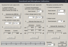
Correct measurement is not done by adjusting fft graph arbitrary to some -xxx dB value, according to our expectations.
In regard of noise level at the standard LM317 output, if 30 dB reduction yields 0.13 uV result, it would imply that ordinary LM317 has less than 2 uV noise at it’s output, which it doesn’t.
What would you say a LM317 + Cadj noisefloor is at? Is that a known value?
LM317 is specified to have noise level 0.003 % of output voltage. For 12V this returns 360 uV worst case. Bypass capacitor is said to reduce noise by 20 dB resulting in 36 uV. Reducing this by 30 dB we get around 1 uV, what is exactly result I got by measuring actual circuit
Correct measurement is not done by adjusting fft graph arbitrary to some -xxx dB value, according to our expectations.
Easy there with such allegations.
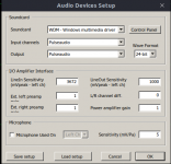
My 0dB point is set at 1.3Vrms which is the max input of my ADC.
edit: my soundcard is a alc892 on a Gigabyte B450 Aorus M
Attachments
Last edited:
LM317 is specified to have noise level 0.003 % of output voltage. For 12V this returns 360 uV worst case. Bypass capacitor is said to reduce noise by 20 dB resulting in 36 uV. Reducing this by 30 dB we get around 1 uV, what is exactly result I got by measuring actual circuit
My measurements are done at around 11.25V as that's what 200R/1.6K results with LM317. 0.003% of that is 337.5uV. If the denoiser offers -35dB over the -20dB of Cadj, then that means 600nV, which from 1.3V means almost -127dB. I will try again with the correct units of measurement as so far I looked at dB for ripple attenuation.
Elvee, the creator of the denoiser circuit tested it himself for noise, and he got less than 0.3uV in 10Hz-10kHz bandwidth with the same BC337 I used:
D-Noizator: a magic active noise canceller to retrofit & upgrade any 317-based V.Reg.
From my 1.3V at 0dB that means almost -133dB. My setup might have some error as I'm using my PCs audio card after all. But not that big of a difference to accuse me of manipulating the results.
If you are going to do that, at least build my v1.4 board as it's really a beginner project, I'm sure you can manage it, measure it on your calibrated gear, and show us how far off I was that I must have manipulated the measurement.
Also you didn't mentioned what circuit you measured, I think that matters a lot. Even if your gear is calibrated, the circuit you measured might not be optimally implemented.
- Home
- Amplifiers
- Power Supplies
- VRDN: bipolar regulator PCB for line level ckts: ±11V to ±20V @ 1.5A with "De-Noiser"