By that you mean to replace the [6n8 and 15Ω] with [3n3] film?
Should one replace the 22μF ecap with 10μF too? In addition to that, would it make sense to replace the BCs with ZTXs?
Sorry if something like that has been asked before, I am reading the D-noisator and VRDN threads for some weeks now, it is a difficult task
Should one replace the 22μF ecap with 10μF too? In addition to that, would it make sense to replace the BCs with ZTXs?
Sorry if something like that has been asked before, I am reading the D-noisator and VRDN threads for some weeks now, it is a difficult task

Yes, all the components should be scaled accordingly, meaning increasing the values, to lower the impedance levels: for example, 6n8 becomes 22nF, 22µ 47or 68µ etc
Great Elvee & lineup!
Lineup, Are we giving it a try? I don‘t have all the components at hand but I will get them in a few days. I’ll post back
@seeyou @Mark Johnson
I have no possibility to build anything at all. I just simulate with SPICE.
But there are a great number of people in this thread that has built the original VRDN in the first post.
Maybe they would be interested to do an upgrade ... ?
6-7dB better does not seem much.
But it is actually half the noise.
But all at a very low level of course
Last edited:
.39R at R3,4,5, and 6 is very annoying! I have to order those, I was so sure they would be in my stock, but nooooo!
Nut+heatsink+TO-220+isolating washer+washer+spring washer+~0.5mm … ca 6-8 mm
Or what you have + a saw and a file. Screw a nut down to the head before cutting the screw, it will clear the thread when you remove it.
Or what you have + a saw and a file. Screw a nut down to the head before cutting the screw, it will clear the thread when you remove it.
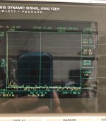
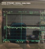
Here are some measurements I made of this circuit yesterday. I wouldn't consider the levels absolute for several reasons but the results are repeatable.
The values are a bit different as some older NJR devices were used. A circuit that can be a bit twitchy but with gain and phase shift what else is new.
Another clever circuit from the minds of the DIY community.
The values are a bit different as some older NJR devices were used. A circuit that can be a bit twitchy but with gain and phase shift what else is new.
Another clever circuit from the minds of the DIY community.
Attachments
Nut+heatsink+TO-220+isolating washer+washer+spring washer+~0.5mm … ca 6-8 mm
I bought 8mm, and with the assembly you described it is perfect. Thanks again.
Hi Wayne,
Are you recommending it to match your designed BA2018 line stage?
If yes, this pretty confirm what I plan to do.
Are you recommending it to match your designed BA2018 line stage?
If yes, this pretty confirm what I plan to do.
Hi Mark..I just want to have this correct since I'm building the wall wart single AC secondary version..so for both the diodes, their bands are at the top when mounted which not so clearly shown as in your pic? It looks almost like the band is down on the BR1 side.Please take a photo from an angle like this one, so the three jumper wires (arrows) are clearly visible. Also, please make sure that your photo shows the "bands" on the cathode ends of the diodes. This picture doesn't show them very well.
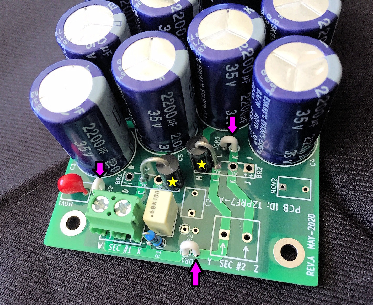
Next, if you stuffed the vertical mount resistors exactly as indicated on the PCB silkscreen graphics, you'll have access to several important circuit nodes via the flying wireloops on the vertical resistors. Please measure the voltages at nodes A, B, C, D and write your measured voltages on the schematic. The fat end of the schematic symbol for vertical resistor, is the abutted end -- the non-flying-wireloop end -- on the PCB. The normal end of the resistor symbol is the wireloop end.
Finally, go to the drugstore and buy a bottle of >90% purity isopropyl alcohol. The one near me sells both 91% and 99%. Also buy a child's toothbrush with soft bristles. Use the toothbrush and IPA to scrub the flux residue off the bottom of your board. Pour about a capful of alcohol on the board, scrub vigorously. Rinse with another 1 or 2 capfuls of alcohol. Repeat 4X. Do the top side too, if it's nasty. You can use a pistol type of hair dryer (cool setting) to dry the board more quickly.
_
The diode should block L going into M but allow C to pass into A, correct?
Thanks, Pete
Last edited:
Hey Pete:
In the first post, Mark had this description for diodes D98 and D99:
D98: Stuff anode in hole "C" and cathode in "A". Solder.
D99: Stuff anode in hole "M" and cathode in ""L. Solder.
Here is that same pic photoshopped to try and make it clearer, albeit while blowing the colors out:

I hope you can see that the left diode is cathode down and the right diode is cathode up.
A pic for reference:

Does that help you?
Nope!.so for both the diodes, their bands are at the top when mounted which not so clearly shown as in your pic? It looks almost like the band is down on the BR1 side.
In the first post, Mark had this description for diodes D98 and D99:
D98: Stuff anode in hole "C" and cathode in "A". Solder.
D99: Stuff anode in hole "M" and cathode in ""L. Solder.
Here is that same pic photoshopped to try and make it clearer, albeit while blowing the colors out:
I hope you can see that the left diode is cathode down and the right diode is cathode up.
A pic for reference:
Does that help you?
- Home
- Amplifiers
- Power Supplies
- VRDN: bipolar regulator PCB for line level ckts: ±11V to ±20V @ 1.5A with "De-Noiser"