Took me about a minute to find it. Thanks to Jason's awesome search engine! Hope this helps...but you already have the answer.Unfortunately, it's near-on impossible to find such a thing in a thread with nearly 4000 posts.
Best,
Anand.
Since your questions are about the BA2018 circuit, and since the Forum members with deep expertise about that circuit are found in the BA2018 discussion thread, it clearly is the most fruitful place to make your requests and entreaties.

This is probably due to a misunderstanding. 25 watts probably only means the maximum power consumption of the built-in 25 watt transformer, not the device.Part of the reason I asked is that, e.g., the XP-20 is said to draw about 25W. That's an order of magnitude greater than the BA 2018. Out of curiosity: Where is all that power going?
However, the XP-20 power supply and preamp combo is a bit more power intensive than normal. The right and left channels have a separate power supply, which of course also means that a bit more power dissipation is required. The electronics in the XP-20 are also somewhat more complex and extensive, which also means higher power consumption.
Due to the separate power supply, the XP-20 also has a significantly lower crosstalk that you can also achieve with your preamplifier if you operate the left and right side with separate VRDN power supplies.
I am having a similar problem with a build that is using an AC wall wart.I wouldn't worry too much about a $50 multimeter whose displayed output voltage flickers between 18.00V and 17.99V. But if you remain deeply, deeply concerned/worried, you could (A) load the outputs with resistors-to-ground which draw approximately the same current as your final audio gear will draw from VRDN; and also (B) monitor the output waveform with an oscilloscope instead of a multimeter.
For example, if your application calls for VRDN to deliver 25mA to the left channel +18V supply, and another 25mA to the right channel +18V supply, that's a total of 50mA from VRDN's +18 output. Ohm's Law tells us that a 360 ohm resistor has the same current draw {math: 18V = 0.05A * 360 ohms} so if you've got a 330 ohm or 390 ohm or 360 ohm resistor, connect it between VRDN +18V and ground, to achieve a same-current load.
V+ I can lock into my desired voltage but the V- dances around and ranges between about 30mv.
is this more of a concern than Namgihinook’s experience?
Update on some things I tried this morning.
Still no luck getting the V- to stabilize. However, after adding the jumpers to bypass the denoiser, the V- stabilized... Hopefully that helps trying to troubleshoot my issue.
- Re soldered all joints on the V- side of the board
- cleaned all the flux off the whole board
- checked orientation of my diodes
- I am using TI regulators, so made sure I had the correct resistor and cap changes
Still no luck getting the V- to stabilize. However, after adding the jumpers to bypass the denoiser, the V- stabilized... Hopefully that helps trying to troubleshoot my issue.
This means that the regulator/denoiser combo oscillates.However, after adding the jumpers to bypass the denoiser, the V- stabilized.
Check the output bypass capacitor, its esr (not too large or too small), and tweak the values of the compensation network: capacitor and resistor if it is non-zero
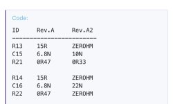
I pulled a 22N Wima off another project and that worked. The V- is solid.
Thanks for the feedback!
Thanks for the feedback!
Hi Mark,
Sorry if this was already been asked:
Can I use BC556 and BC546 as substitute for BC337 and BC327 (Q1 & Q2)?
Thanks for reply.
Sorry if this was already been asked:
Can I use BC556 and BC546 as substitute for BC337 and BC327 (Q1 & Q2)?
Thanks for reply.
Thanks Elvee, I'll see if I can find BC337/327.
Also, if I target +-18Vdc out, what would be the output Vac dual secondary winding of transformer to use for the BOM posted?
Also, if I target +-18Vdc out, what would be the output Vac dual secondary winding of transformer to use for the BOM posted?
Any problem using this as a turntable power supply? I know the denoiser would not be needed but I have a board I built up to use with AC wall wart and can get 12V for my Clearaudio Concept turntable.
Will STMICROELECTRONICS LM317BT work instead of the onsemi part(specs look the same)? only sub I can find at Newark currently.
If you get no response about extra boards for sale try jlcpcb. Download the Gerber file from the first post and then upload that to jlcpcb. It's a fun and relatively easy process.

Hello! I'm about to make my own VRDN version with some few tweaks (adding a 5V rail, different heat sinks, connectors, etc...).
So first of all thanks a lot for sharing the design, it made me gain a huge amount of time and head scratching!
I'm still left with a few questions, so here we go:
1 - Does the design really benefits from having 4 layers or could I go with just 2 (with 2 ground planes)
2 - What about earth? Would it be a bad idea to tie it to ground in this design?
3 - I can't decide which trafo to use, there are too many lol. Any recommendations?
- http://www.hammondmfg.com/pdf2/1182J18.pdf
- http://catalog.triadmagnetics.com/Asset/VPM36-1390.pdf (or) http://catalog.triadmagnetics.com/Asset/VPT36-1390.pdf
- https://talema.com/wp-content/uploads/datasheets/Open-Style-230V-Primary-0050VA.pdf
- https://sklep.toroidy.pl/en_US/p/TTSA0050-Transformer-AUDIO-TSA50VA-voltage-to-50V/309
Thanks!
- Home
- Amplifiers
- Power Supplies
- VRDN: bipolar regulator PCB for line level ckts: ±11V to ±20V @ 1.5A with "De-Noiser"