That totally depends on the Vas, but yes they have a HP effect because of the stiffness.Passives drop pressure very fast at LF due to self resonance so adjustment with levels is inaccurate...almost impossible
Something a port doesn't have (or at least not a significant amount of).
See the lumped analogy models.
A PR is also only as accurate as its Kms(x).
Data that is never ever shown.
I actually even wonder how that can be measured and/or if that even has been done?
Because saying that a PR has a max excursion has a xmax of 9mm (eg) doesn't mean much if we don't know if that is at 75% Cms or 50% Cms.
We also have zero clue how symmetrical that is.
So it could be as well that a certain PR is very much out of balance or acting very unstable.
Last edited:
Member
Joined 2003
Yes, that's the one I was speaking of. Both VituixCAD and REW include built-in calculator tools for measurement compensation using this method, so no complicated math is required.I have found that Microphone-in-box method as described by Joseph D’Appolito here:
https://audioxpress.com/article/measuring-loudspeaker-low-frequency-response
gives a very good low frequency response directly without need for scaling between woofer and port.
Above 150 Hz or so (where the port is usually inactive) you can merge to the near field response of the woofer.
Then the above summed response can be merged to the Far field response taken at 1 or 1.5 meters.
The inbox method is extremely tricky from a practical point of view.I have found that Microphone-in-box method as described by Joseph D’Appolito here:
https://audioxpress.com/article/measuring-loudspeaker-low-frequency-response
gives a very good low frequency response directly without need for scaling between woofer and port.
Above 150 Hz or so (where the port is usually inactive) you can merge to the near field response of the woofer.
Then the above summed response can be merged to the Far field response taken at 1 or 1.5 meters.
Not only do you have to be very careful with the position of the microphone.
Even if we assume we are far below the first modes of the cabinet (like room modes have a Schroeder frequency), the output can change quite dramatically per position (close to a wall, in the middle, semi in the middle, close to a driver etc etc)
But also we have to make sure we don't clip the microphone.
Turning the volume down also has its downsides, since some speakers will behave differently since the BL and compliance are not the same at those low levels.
In the field of general acoustics they often uses similar systems for calibration purposes.
From my experience and background in that field, I know that losses also don't always translate all that well to actual "in-room response"
So the article shown misses a very fundamental step, which is showing and comparing the results with "actual" measurements, like from a very good anechoic room or a Klippel NFS system.
Meaning we can only see a difference between two methods, we only have no clue which one is more accurate.
They even could be both wrong, who knows.
It also doesn't show the off-axis response, so again assumes that the low-end is omnidirectional.
We can't draw any definitive conclusions from this article.
Yes, I agree.
The position of the mic in the box is very critical, but it is not difficult to find one position that it does not have the problems you refer.
And you need a microphone to accept the high pressure. I use a modified (as proposed by Linkwitz) Panasonic capsule with very good results.
Concerning the other things you mentioned, are you saying that the near field measurement and the microphone-in-box measurement are not accurate at all?
Then what is left for us without a anechoic room or a proper place for groundplane measurements ?
Could you propose something else ?
The core problem as a red line through all posts here is the lack of an absolute reference for the low frequency response. Even the much referred to Klippel NFS is to my very limited understanding just estimating the low frequency response.
So the much mentioned "error" is an unknown and probably remains so. If with "error" is ment the spl response, in my scope being sealed box, i doubt if the deviation from the absolute is significant when applying stitching near/far measurements (mib or 5mm from cone etc) and using the bafflestep impact at 3m 5m using Vituixcad. However the phase response at low frequencies i have more doubts about.
So the much mentioned "error" is an unknown and probably remains so. If with "error" is ment the spl response, in my scope being sealed box, i doubt if the deviation from the absolute is significant when applying stitching near/far measurements (mib or 5mm from cone etc) and using the bafflestep impact at 3m 5m using Vituixcad. However the phase response at low frequencies i have more doubts about.

I don't totally agree with that.The core problem as a red line through all posts here is the lack of an absolute reference for the low frequency response. Even the much referred to Klippel NFS is to my very limited understanding just estimating the low frequency response.
So the much mentioned "error" is an unknown and probably remains so. If with "error" is ment the spl response, in my scope being sealed box, i doubt if the deviation from the absolute is significant when applying stitching near/far measurements (mib or 5mm from cone etc) and using the bafflestep impact at 3m 5m using Vituixcad. However the phase response at low frequencies i have more doubts about.
It's only that the more complex you make a system, the less predictable this low frequency part becomes.
A closed system is very predictable, some kind of complicated horn system a lot less.
On the other hand, there is also definitely an argument to be made how important that is.
Because room modes will make total garbage out of any low-end.
Well, I say that with a little asterisk, because really poor designed low-end still sounds terrible.
The question is not if we have errors, but how big those errors are.
Absolute measurement results are by definition not possible, otherwise we will run into issues with statistics as well as Heisenberg.
Besides these predictabilities, the more complex a system becomes, (like the higher order it is), the errors also will (and must) get bigger.
Oh yes the more complex the more unpredictable. The error is therefore undefinable. But as you also said the impact of boundaries makes it in my view also not so significant, at least for the amplitude/spl.
Regardless of what happens to that bass in a room, the anechoic bottom end of the woofer response still represents the baseline sensitivity as it would without the room. Go ahead and incorporate a multi-sub system and you tweak the output over the space, up and down as required, about that baseline. Not only is this the path to a smooth transition but it includes the mains in the blend. After that, contouring is optional.
Yes, but there is a bit of room for error here.the anechoic bottom end of the woofer response still represents the baseline sensitivity as it would without the room.
It's most definitely not as sensitive as most people think it is.
So we don't have to pixel peep over certain details.
Even more so if we take large signal behavior into the equation.
Hi folks,
I'll be using REW and Vituix for the first time to design a speaker crossover. The project is a 40cm wide baffle TMM 2.5 way with Vifa MG18WKs and Peerless DX25 mounted on a WG148 Visaton waveguide. The bottom midwoofer will be used as BSC.
The question is, the two midwoofers share the same box and need to be measured connected together, correct? But how to isolate them when drawing far field responses?
Or far field responses could be measured with separately connected midwoofers, gated measurements with no supposed influence from the box, but near field measurements with both of them connected? Then merging the responses?
What about impedance measurements?
Member
Joined 2003
Yes, far field can be measured with each driver individually. Of course, the cabinet response will not be correct with only a single driver playing, but only affects the low frequency portion that won't be captured in a far field measurement.
Near field requires both woofers connected to capture the correct cabinet response, you may try playing a pillow in between to reduce influence from the second woofer for the near field measurement.
Same for impedance, it requires both driver connected to capture the correct cabinet response. The measured impedance of both drivers may be used individually for each driver in VituixCAD, with scaling set as either 0.5 or 2 depending on whether the drivers were connected in series or parallel.
Be sure to read through the measurement guide for REW, much of this is captured in there.
Many thanks! Second question. For far field individual driver measurements, should the other driver be shorted, to avoid acting as a passive radiator, or leads should remain open?
Member
Joined 2003
I tried and didn't save the measurements, but above 100Hz they looked identical. Below that, the frequency response shape of the setup with non-shorted driver is also the same, just -2dB decreasing in amplitude, compared to the shorted driver.
Member
Joined 2003
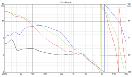
Quick questions. When aiming for good phase alignment, in Vituix, what are the priority targets to look for in the GD & Phase window? I'm currently prototyping the crossovers of the 2.5 way project. The blue line represents the waveguide loaded tweeter, whereas the green one depicts the midbass driver. As I've heard from other folks using Vituix, the Lines should interleave as most as possible, but at what point is the priority one? The crossover point?
Attachments
Member
Joined 2003
Phase alignment through the frequency range where both drivers are playing together, of course...It is very clear in directivity data, however it appears you have not followed the measurement guide to provide any directivity information, so that would be my focus.
Hi, I am measuring +- 90 degrees horisontally a two way ported speaker using Focusrite 2i2 with loopback timing and EMM6 mic. The tweeter is Seas millenium and woofer is Seas W18E001. Reason for measuring is for crossover simulation.
Should i place the mic centered between tweeter and woofer for far field measurements, and measure each driver far field without adjusting mic height?
Or set height when measuring tweeter so mic is on the same height as tweeter? And adjust mic height for woofer measrement with mic on woofer height axis?
- Home
- Design & Build
- Software Tools
- VituixCAD