Is this the case with time reference measurements?I agree, but with the caveat that you must maintain the exact same distance from mic to baffle for both woofer and tweeter measurements. By exact, I mean +/- 1 mm. If your setup does not allow you to maintain that level of distance control, then you should use a fixed mic position for both drivers. In this situation, I usually select a mic height that is midway between the two drivers.
Sorry I didn't notice the mistake early enough to editMoving the mic around the speaker in a normal room (not anechoic) will make variance in reflections, so one must use very short gating. When rotating mic reflections are constant (only some variance in amplitude), and normalization works well and you can identify and ignore them easier in your mind too.
When rotating the speaker, reflections are constant (only some variance in amplitude), and normalization works well and you can identify and ignore them easier in your mind too.
It is rather easy to diy a turnable from two plates of MDF, the upper's another half rounded and marked 0-180 deg, and center turnpoint pin. Then just a kitchen ladder or something like it to elevate the speaker to desired height. The table just under the DUT should not be wider than the speaker box!
My setup


It does not matter what you rotate because whole purpose is to produce far field anechoic data i.e. all reflections should be cropped out with gating. Difference is that mic rotation requires 2-3 times more floor space than speaker rotation. Mic rotation could be valid with in-wall and on-wall or with very heavy or complex speakers.
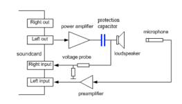
It's just the amp output signal to the speaker but directly fed back to the right channel input of the sound card. If you use a power amplifier (the normal case) use a voltage divider to protect the soundcard input from high voltages.But I can't find any information about what that is exactly?
Member
Joined 2003
In the link above, the author gives us a specific instructions to avoid using a bridged amplifier when a voltage probe is used. This is important. I broke some equipment (audio interface and a laptop) because I did not know the amp I was using was internally bridged. Now I check new amps to be sure that speaker (-) is actually tied to ground.
Bridged amp = differential signal = XLR
So yes, you can just very simply hook up a bridged amplifier to a XLR input, as long as you respect the maximum voltages.
Since most audio interface have 48V phantom power (otherwise you also wouldn't be able to use a mic), they are usually fine up to either 50V or 63V DC.
Be aware that most of those simple Class-D amplifiers that are bridged don't have post-filter feedback.
Which makes them not very well suited for measurements.
I plan to measure a downfiring subwoofer as shown in the attached figure.
I will measure it with two ways:
a. With the Microphone in the Box method and
b. By merging the Woofer and the Port responses with the mic positions as shown.
What do you think?
1. Is there a better mic position especially for the woofer?
2. Should I correct the response for diffraction? Or since it is placed on the floor, it will radiate in 2π ?
Attachments

It is possible that the mic on the floor will give you a valid response. But it is also possible that it will not. It is a non-standard method, so it is hard to say how much accuracy you will loose compared to the standard methodology.
If you want to be sure of a good measurement, put the woofer mic on the center of the dust cap, with a clearance gap of 5-10 mm. That would be my suggestion...
If you want to be sure of a good measurement, put the woofer mic on the center of the dust cap, with a clearance gap of 5-10 mm. That would be my suggestion...
In the Enclosure tool, with the exception of the SPL graph, I can't find how to change the Y-axis limits.
I am trying to run a simulation at 100W. The Power graph data is obviously beyond the 2W power graph limit.
I'm clueless? A bug? Feature request?
I am trying to run a simulation at 100W. The Power graph data is obviously beyond the 2W power graph limit.
I'm clueless? A bug? Feature request?
Also some bridged-only amps (such as ICEpower ASC-200) have moderately high DC voltage sitting on the outputs with respect to ground.... So yes, you can just very simply hook up a bridged amplifier to a XLR input, as long as you respect the maximum voltage
You might consider the technique proposed here:1. Is there a better mic position especially for the woofer?
https://www.klippel.de/fileadmin/kl...39_Merging_Near_and_Farfield_Measurements.pdf
If this is really a subwoofer there will be no relevant cabinet diffraction at low frequencies. Also the response will not follow an idealized 2pi radiation but will entirelly be dominated by room modes.2. Should I correct the response for diffraction? Or since it is placed on the floor, it will radiate in 2π ?
You could simulate the in-room-response with the jeff bagby excel tool and correct the nearfield measurement accordingly:
http://audio.claub.net/software/jbabgy/BDBS.html
I think vituixcad can do something similar.
But a 2pi approximation is probably a good first estimation.
Member
Joined 2003
VituixCAD has "room" tab, however REW has a more functional room simulator for bass modes. BDBS is BS by comparison. In either case, room correction should be completed with room measurements, not simulation. Verification / validation of cabinet design can be done in the near field.
Last edited:
To get an indication of the room modes, so to understand better the measurements, trythis link as i used it myself as well:
Interesting new feature at https://amcoustics.com/tools/amroc-pro , non shoebox room models:

Here a floorplan of my groundfloor.
Seems to correlate reasonably well with measured room modes.
Here a floorplan of my groundfloor.
Seems to correlate reasonably well with measured room modes.
Thank you all for your responses.
But I have to say that my main interest is to measure the subwoofer in "anechoic conditions" without the effect of the room.
And since the woofer is facing to the floor, I was wondering what should be the correct position of the microphone for the near field measurement.
But I have to say that my main interest is to measure the subwoofer in "anechoic conditions" without the effect of the room.
And since the woofer is facing to the floor, I was wondering what should be the correct position of the microphone for the near field measurement.
The floor is part of the room, so why not measure the driver output in classic nearfield situation then (mic ~5 mm distant from dustcap)?my main interest is to measure the subwoofer in "anechoic conditions" without the effect of the room.
Nearfield/anechoic by definition is very near to the diaphragm, excluding any other influences (also the floor).And since the woofer is facing to the floor, I was wondering what should be the correct position of the microphone for the near field measurement.
But I guess the ideal measurement for you would be a ground plane measurement outside, far from any other surfaces, except the floor, of course.
Edit: or use the mic-in-box method! Scroll down in this article:
https://audioxpress.com/article/measuring-loudspeaker-low-frequency-response
As far as I know REW has a tool for creating "classic" response graphs using this method.
Last edited:
In a german forum a box was send around to different persons to measure in any different way, including klippel. The person who organised it is also active on this forum but i forgot his name. Anyhow it showed that a measurement very close ( few mm) to the driver is as good as klippel or groundplane or mib.
- Home
- Design & Build
- Software Tools
- VituixCAD