this ^^^Or set height when measuring tweeter so mic is on the same height as tweeter? And adjust mic height for woofer measrement with mic on woofer height axis?
Follow the recipe/manual-
"Read Measurement with CLIO or ARTA or REW or SoundEasy. This is mandatory document to read and follow to enable fast and controlled speaker simulation producing accurate off-axis simulation and reliable power and DI responses."

I agree, but with the caveat that you must maintain the exact same distance from mic to baffle for both woofer and tweeter measurements. By exact, I mean +/- 1 mm. If your setup does not allow you to maintain that level of distance control, then you should use a fixed mic position for both drivers. In this situation, I usually select a mic height that is midway between the two drivers.
Really?I mean +/- 1 mm
1 mm is the wavelength of a 340 kHz "tone".
Or 21° phase error at 20 kHz.
Or 2° phase error at a common crossover frequency of 2 kHz.
Or it means an offset angle of 0.6° considering a tweeter/mid distance of 100 mm.
Or a heigth deviation of 1 cm in case of 1 m measuring distance for the same driver distance.
But I am very happy to be corrected, since I am just diving into vituixcad!
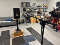
I measured with the mic constant, only rotating the speaker. The manual for Vituixcad shows rotating the mic, but that is alot more work... And seems like alot of people are only rotating the speaker. But are you also moving the mic accordingly so you have 1 meter to driver at all angles?
It does not matter which one is rotated. Measurement instructions show which direction is positive and which is negative. I can reveal that also author of VituixCAD rotates speaker with Outline ETThe manual for Vituixcad shows rotating the mic, but
When I run simulations in VituixCad of a 2-way crossover, I usually can see a small change in response by varying the z-dimension by 2 mm (i.e. +/- 1 mm). Of course it is just a barely detectable difference, the width of a line, but it is enough change in z to cause some variation in response. In the plot below you can see a small difference.
2 mm variation (+/- 1 mm)

Now of course this is a trivially small difference, well within the measurement uncertainty. But the alternative, a fixed mic position, really has no downside when applied to a midrange+tweeter situation.
With a good mic stand, it is quite possible to adjust the height and keep the distance constant. My advice is meant for situations where a good mic stand is not available.
6 mm variation (+/- 3 mm)

2 mm variation (+/- 1 mm)
Now of course this is a trivially small difference, well within the measurement uncertainty. But the alternative, a fixed mic position, really has no downside when applied to a midrange+tweeter situation.
With a good mic stand, it is quite possible to adjust the height and keep the distance constant. My advice is meant for situations where a good mic stand is not available.
6 mm variation (+/- 3 mm)
Every microphone stand with boom bends more or less when the height is changed, so the distance should be checked and adjusted if necessary.With a good mic stand, it is quite possible to adjust the height and keep the distance constant
Maybe i am asking stupid questions, but what then when measureing at -180 on x axis. So you dont have to then move the mic closer, aproximately the same as depth of the speaker...?
When doing horizontal polar scans, the vertical axis of rotation normally aligns with the baffle. There are probably some odd-ball exceptions, but generally this is the rule.
Yes, but i am wondering about the mic distance to the driver on the horizontal axis when turning the speaker. Surely the distance is not the same at -180 degrees horisontally as on 0 degrees if the mic is not moved
Ok I see what you are getting at...
If the drivers are arranged vertically centered on the baffle, the path distance will remain constant as the speaker is rotated from 0 - 90 degrees. From 90 to 180 degrees, the path distance (time of flight) will increase with each rotation angle as the sound must travel around the baffle and the side of the speaker.
The clever algorithms within VituixCad account for this effect. The differences in time of flight are merged into the phase response for each angle.
Discovered that some resistors had almost caugt fire to the crossoverboard. 😱 Therefor i am measuring and adjusting the crossover.

Member
Joined 2003
I did use that power dissipation funtion, so i had two in parallell. But i will now be sure to allow for more headroom in power dissipation. And also not place the crossover board directly against the inner wall of the enclosure, make some spacers in between.
Moving the mic around the speaker in a normal room (not anechoic) will make variance in reflections, so one must use very short gating. When rotating mic reflections are constant (only some variance in amplitude), and normalization works well and you can identify and ignore them easier in your mind too.
- Home
- Design & Build
- Software Tools
- VituixCAD