Thanks. That's what I figured. 😛No. Few library blocks are available for passive and active 2- and 3-ways, and optimizer supports iteration of block attributes suct as XO frequency and Q factor too. Any project can be used as starting point/template for other project. Ideal flat axial response can be created for active FIR using IR file. That is closest to designing XO producing ideal flat minimum phase response in a minute. So program is primarily versatile pro. Not for very beginners who don't know how XO components and blocks work.
Last edited:
Instruction is not detailed. Basically you just export transfer function at driver terminals as impulse response files - typically IEEE mono or stereo wav. Before exporting you need to select Fs, taps and window function. Centered unchecked and pre-delay for example 0.5 or 1.0 ms for emulation of passive crossover which is IIR without latency. Export window supports exporting max. 6 drivers at once. Typically one file for each way. Then you load these IR wav files to different channels in Equ APO application. Each file to left and right channel if they are mono. That's it. You have passive XO emulation with FIR engine in PC.kimmosto, Is there a tutorial on how to create an active FIR filter from a passive design? I saw the section in the document, but not able to understand 100% how to do it.
Member
Joined 2003
Thanks a lot for that basic instruction Kimmo, this may be quite useful for a few people who may be interested in moving from SoundEasy to VituixCAD, but keeping SoundEasy for the "digital filter" function that will simulate the passive filter transfer function using the PC soundcard. I know that simulation of passive filter transfer function is an often requested feature, where the only software that I know that offers it directly is SoundEasy.
If I can get this to work successfully I will make it into a nice step by step instruction.
If I can get this to work successfully I will make it into a nice step by step instruction.
Also LspCAD has convolution with impulse response. Emulating passive XO is not important/useful anymore in my opinion. Measurement and design methods are good, and sound quality and compatibility of drivers can be tested with active system. In addition, emulated passive does not give exactly the same result with real passive due to different source impedances and component features. Current/voltage driving properties have impact for example to non-linearities and handling of back emf.
Member
Joined 2003
Yes, I would agree with you, however for new users, even with the differences that can be presented of an active filter simulation of a passive filter transfer function, being able to listen to the result and make changes to the response and listen again can help put the charts and graphs into context, creating a better correlation between what you see on the screen vs real world audible result. Of course, you could just get a DSP for the same insight, but often a passive filter is the end design goal and a user wants to purchase crossover parts once with confidence.
Member
Joined 2003
Hi Kimmo, I just went through the impulse response export - APO EQ process, and it was almost too easy! Very suprising, I verified with ARTA loopback, the result is exactly as EQ APO says it is. Really cool stuff.
Quick question on the Impulse response export, for the purpose of exporting a filter response transfer function, is there any reason not to simply use the maximum FFT length and many taps?
Quick question on the Impulse response export, for the purpose of exporting a filter response transfer function, is there any reason not to simply use the maximum FFT length and many taps?
Member
Joined 2003
Long FFT length is not a problem. Just slower, but it does not matter in this window. For example 64K with already good LF resolution is usually adequate for any purpose.Quick question on the Impulse response export, for the purpose of exporting a filter response transfer function, is there any reason not to simply use the maximum FFT length and many taps?
Number of taps (and high Fs) can be really problematic in practice due to CPU load and possible limits in DSP gear. Not with Equ APO and other applications running in high performance multi-CPU system. Pro DSP gear could have very limited number of maximum taps because long latency is not accepted. For example totally 2048 for all ways of multi-way so you have to distribute taps based on frequencies requiring some filtering; 1024 for LF, 768 for MF and 256 for HF or so.
Different number of taps for different drivers/ways is not yet properly supported in Impulse response window. Problem is gain normalization requirement for certain IR file types. Program searches highest impulse value from all drivers and normalizes that individual to max 1.0. Others may have lower maximum due to different gain. Workaround is to export all driver inputs with different taps to different directories and finally pick combination suitable for DSP gear.
Member
Joined 2003
Thanks, you’ve confirmed my thoughts. With EQ APO there really isn’t any concern of processing horsepower even with a low end CPU, so using many taps is not of great concern.
I will update the instruction shortly, there is a missing step to use “copy channels” in EQ APO to copy left and right channel to all outputs used
I will update the instruction shortly, there is a missing step to use “copy channels” in EQ APO to copy left and right channel to all outputs used
The minimum amount of taps you get away with also really depends on the type of window.
When there are very limit resources (like an ADAU1701) one will get very creative with this after a while.
To be honest using FIR for just a filter comparison is also rather overkill, just remake the filter response with IIR is more than good enough. The benefits of FIR are many orders of magnitude less important than a different crossover (frequency) with the DI that is always involved with that as well.
Any PC from the last 5-10 years has an overload of processing power, so no amount of taps is never a concern, unless you go WAY overboard with it. RePhase is also a nice tool to optimize FIR taps.
Hello DecibeL,
Just read your tutorial. Thanks very much for this nice write-up.
A question: you write: we are exporting a full frequency response.
This sentence puzzles me somewhat: shouldn't we be exporting each filter leg, transfer function in dB/freq. converted into an IR and then exported in .wav format into EqAPO separately, or am I misunderstanding matters here?
Member
Joined 2003
Yes, you are exporting the filter transfer function for each leg, and the "full frequency response" of it. What is meant is that we capture the frequency response of the filters from 20Hz-20kHz without being limited by the windowing function, so you can consider the exported result "ungated". Perhaps I could change the wording here somewhat for clarity.Hello DecibeL,
Just read your tutorial. Thanks very much for this nice write-up.
A question: you write: we are exporting a full frequency response.
This sentence puzzles me somewhat: shouldn't we be exporting each filter leg, transfer function in dB/freq. converted into an IR and then exported in .wav format into EqAPO separately, or am I misunderstanding matters here?
Member
Joined 2003

2.0.82.0 (2022-01-17)
Preference rating- Added 'custom' equation including SM_ON, SM_LW, SM_ER and SM_SP with adjustable weight 0-2 for each.
Option is designed for Optimizer. Initial weighting factors: SM_ON=0.5, SM_LW=1.0, SM_ER=0.75 and SM_SP=1.5.
SM values are calculated within 130-16000 Hz instead of standard 100-16000 Hz. Maximum rating is 10.
Also this equation requires target for SL_ON or SL_LW (or both) to be stable while optimizing. - Added SM_ER and slope_ER values to PR table.
- Removed PIR weight information.
- IEEE 32/64-bit wav files are exported without normalization to max 1.0 to include gain differences also when individual IR files are exported with different taps and IR window.
- Removed PIR weight LW, ER and SP text boxes.
filter simulation.pdf may require some update due to previous in red.
I will change low limit of taps later to support at least down to 128.
I will change low limit of taps later to support at least down to 128.
Member
Joined 2003
Thanks for the update, the change to the behaviour of the IR export is a welcome one. I don't think the instruction requires update to reflect this though, just less chance of error in gain if someone deviates from what I've written as a step by step process.
L-R transfer functions are phase matching in 2-way only so there will be some difference if speaker is 3+way and phase responses of IIR version are not matched e.g. with all-pass stages.
Member
Joined 2003
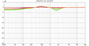
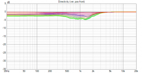
With the aid of some very helpful information provided by Kimmo over at HTGuide, I have assembled another instruction for using "mirror EQ" with VituixCAD. This can be used in conjunction with APO EQ to provide a completely normalized axial or listening window driver response, similar to the functionality that Bodzio Ultimate Equalizer provides.
The attached instruction is to be used in conjunction with the filter simulation with APO EQ that I posted above:
https://www.diyaudio.com/community/threads/vituixcad.307910/post-6910988
The attached instruction is to be used in conjunction with the filter simulation with APO EQ that I posted above:
https://www.diyaudio.com/community/threads/vituixcad.307910/post-6910988
Attachments
- Home
- Design & Build
- Software Tools
- VituixCAD