^You can also play without active TF block by processing acoustic measurements with Calculator tool. Divide measured acoustical responses (A) by electrical transfer function at driver terminals (B). Response B should be scaled so that gain=0 dB at HF. Result is response without series capacitor (and possible shunt resistor).
Impedance response should be measured without extra components of course.
i did some tests last night, i measured the response with a cap, measured the driver impedance without cap, simulated the filter transfer function for the cap and the measured impedance, then by calculation removed the cap function from freq response with the cap, and it worked
what a pain, an inverted cap function in vituixcad would make this so much easier 🙂
or a more simple cap remover calculator in vituixcad 🙂
Some care needs to be taken though
it sounds like the mls signal stresses the driver much less then the noise stimuli, even when using a very high cutoff frequency.
how about the very low impedance of the ribbon driver, is it not a problem for the amp?
also, when using my laptops headphone out/mic in for impedance measurement i can hear a small pop when connecting a driver to the testleads, there seems to be a small dc voltage output present at the input, a voltage power for a condensers mic i guess, can this smallish voltage do any harm?
an inverted cap function in vituixcad would make this so much easier 🙂
That wouldn't be difficult to add assuming that value of entered "protection capacitor" is accurate and output impedance/resistance of amplifier is known.
how about the very low impedance of the ribbon driver, is it not a problem for the amp?
This was already answered #2532
That wouldn't be difficult to add
Already done & tested but who would understand this?
Attachments
wow, that is super cool 🙂 any ribbon user will use it regularly
will that work for impedance also, like that protective cap is used for acoustic measurement as well as for electric?
will that work for impedance also, like that protective cap is used for acoustic measurement as well as for electric?
Already done & tested but who would understand this?
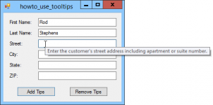
I haven't tried VCAD yet, but if it's not yet implemented, then implementation of tooltip would be very helpful.
Tooltip - Wikipedia
Use tooltips in C# - C# HelperC# Helper
Attachments
Would it be clearer as a Calculator function?Already done & tested but who would understand this?
^Agree.
2.0.58.4 (2020-12-17)
Calculator
* Added 'Protection Capacitor A z B' function. Compensates effect of protection capacitor in series with driver while frequency response measurements.
2.0.58.4 (2020-12-17)
Calculator
* Added 'Protection Capacitor A z B' function. Compensates effect of protection capacitor in series with driver while frequency response measurements.

will that work for impedance also, like that protective cap is used for acoustic measurement as well as for electric?
No. Impedance response should be measured as usual - with series resistance only. R=27...400 Ohms.
Measured impedance response of driver is needed as response B in Calculator. See user manual for more information.
^VituixCAD is simulation program, and everything I have published for measurements is for producing measurement data for simulation.
Phase does not matter i.e. can be anything or totally missing if you use SPL (phase hidden), Power & DI and Directivity charts of the main program for QC measurements of complete speaker with crossover.
BUT if you like to see actual phase and actual group delay in GD & Phase chart, you must use actual measured phase. Not minimum phase extraction because it destroys phase response of multi-way with normal IIR (not linear-phase FIR) crossover.
***Hello! I have sent you a couple of questions by email. I think it is not correct to discuss this here on the forum. Witness it please! Thank you!
Calculator
* Added 'Protection Capacitor A z B' function. Compensates effect of protection capacitor in series with driver while frequency response measurements.[/QUOTE]
Does impedance need to be measured with C also?
EDIT: disregard, didn't see Celef asked already, and it was replied to.
* Added 'Protection Capacitor A z B' function. Compensates effect of protection capacitor in series with driver while frequency response measurements.[/QUOTE]
Does impedance need to be measured with C also?
EDIT: disregard, didn't see Celef asked already, and it was replied to.
Crossover simulation in the main program does not need and cannot handle anything extra in impedance response file so it's perfectly natural that impedance response is measured normally - with series resistor only.
For all: just follow measurements instructions and user manual.
For all: just follow measurements instructions and user manual.
What a great idea.^Agree.
2.0.58.4 (2020-12-17)
Calculator
* Added 'Protection Capacitor A z B' function. Compensates effect of protection capacitor in series with driver while frequency response measurements.
I'll give this measurement method a try on my next design which will also have Ribbon tweeters as I was never completely happy with the measurements I took using dual channel mode for compensation of the protection capacitor.
Judging by the screen shot this correction is applied to the imported FRD response of the driver, (so the frd file would always have the roll off of the cap) would it have been better to include it in the impulse response processing tool to apply the correction permanently when converting an impulse to an frd ? In that case you would process the impulse response once with the special knowledge that the effects of a capacitor were included in the measurement, and the frd exported would then be compensated and able to be used in the project without retaining that special knowledge of a capacitor value in the project file.
Edit: Thinking about this it would not be so easy as the Impulse conversion tool would then need to be able to import the impedance curve of the driver as well which it currently doesn't.
Last edited:
Working with impulse response does not make any change other than more complex calculation and work for me.
Advantage of calculated series reactance by protection capacitor is full level of reference signal because reference channel is connected to output of sound card or power amplifier - before high-pass filter. Also simpler measurement and post process.
But that does not help with noise at LF in measurement channel. As already mentioned, noise much below final high-pass by XO is not dangerous. One option to reduce measured noise is to protect with (active) shelving high pass e.g. -20 dB. That could help with ATM and magnetostatic planar, but not with true ribbon because they cannot produce pressure at LF. One possible math trick could be cropping LF, extending slope down as minimum phase and merging to response with measured phase.
hmm, i do not get this to work, if i understand this right; 'a response' is supposed to be the freq response with protective cap, and 'b response' is supposed to be driver impedance, but there is no option to choose an ZMA-file, do i need to convert my ZMA-file to txt-file to make this work? and the impedance measurement response curve should contain an added 27-100 ohm series resistor?
I have tried this a number of times now but I can not get the calculations to match my reference curves, I think the method works too non-intuitive for me, but thanks for your effort 🙂
^Program does not care is file extension txt, frd or zma. All the same text files. zma files are possible to show by entering *.zma to filename or load directly to response list with drag&drop. Standard windows features - intuitive or not.
Anyway, the latest build has also *.zma in both file extension list.
Anyway, the latest build has also *.zma in both file extension list.
User manual says:
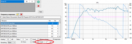
Protection Capacitor A z B
Compensates effect of protection capacitor in series with driver while frequency response measurements with semi- or full dual channel mode i.e. reference channel is connected to output of sound card or power amplifier. Not between protection capacitor and driver!
Load frequency responses (txt/frd) to A and impedance response (txt/zma) to B. Verify that Linear input mag A and Linear result mag are unchecked, and Linear input mag B is checked. Enter series capacitance to C/uF text box.
Default result filename extension is uncap.txt.
- Home
- Design & Build
- Software Tools
- VituixCAD