^That's correct.
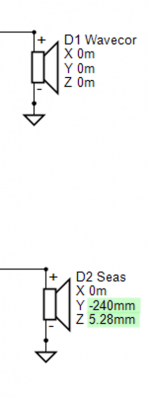
Just note that Z mm of driver instance in XO is 0 mm and Delay offset of driver's response data is 0 us if you work according measurement instructions with straight non-stepped and non-tilted baffles because mechanical rotation center while off-axis measurement sequence is at level of baffle surface and timing reference while converting impulse response (semi-dual channel) measurements to frequency response is equal to all drivers. So timing difference of drivers is included in measurement data only, and XYZ of driver instance equals to mechanical rotation center (relative to speakers origin) while off-axis measurement sequence.
In addition, Delay us parameter should be used instead of Z mm for drivers in boxed speakers with straight non-stepped and non-tilted baffles if measured or traced response data is normalized or processed with minimum phase extraction, because Delay works better than Z to high off-axis angles. This was not significant decades ago when speakers were designed with axial response only, but now situation is different with VCAD and others which calculate off-axis too.
All this should be mentioned in measurement instructions and user manual so please read those to get original info asap.
Rev. 2.0.36.0 (2020-02-19)
Main
* Added File->Export->FIR transfer function for Driver i.e. driver's linear-phase target response divided by raw response to reference angle.
Nice pratical and spare some calculation work, thanks 🙂
^Simple target response divided by measured+merged response works okay for mids and tweeters but woofers need some workaround and possibly manual tweaking because HP slope at low end should be minimum phase. Not linear-phase.
Thank you to Kimmo Saunisto for this wonderfull software😛, very very gratefull.
it is very complete and powerfull, but you need to know well loudspeaker design.
Software
thank you again.
very interesting for the synergy horn, special the filter design.
regards
Thanks guys! Hopefully I can keep this software alive and add some new features in the future, though new ideas and motivation are slowly decreasing. Maybe because it's already so perfect 😀
-Kimmo
Hi Kimmosto
It is very beautifull software, keep it going, helping world community gives the best boost in live you can imagine, feeling good..
regards
...woofers need some workaround...
Not anymore because
Rev. 2.0.37.0 (2020-02-21)
Main
* Added lin.pha checkbox to High pass and Low pass slopes of driver's target response in Optimizer window. Enables selection of minimum phase or linear phase target slope for File->Export->FIR transfer function for Driver.
* Added 'Driver target phase' curve (magenta) to GD & Phase chart.
Rev. 2.0.37.1 (2020-02-23)
Main
* Added Invert checkbox for driver's target response in Optimizer window.
Helps creating phase targets for textbook IIR crossovers (implemented with FIR).
Main
* Added Invert checkbox for driver's target response in Optimizer window.
Helps creating phase targets for textbook IIR crossovers (implemented with FIR).
Last edited:
IR export of driver input
Hi Kimmosto,
While exporting the driver input impulse responses I noticed something odd in the high pass section. I have had the same issue with multiple projects now. To illustrate the issue I will use your "epe-3W_demo V2" project.
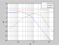
I exported the IR's of the 3 driver inputs with the settings shown in the first image. After that I plotted the frequency responses of the 3 IR's. The low pass and bandpass sections are equal to the filters shown in Vituixcad. However the high pass sections seems to be wrong.
Do you have any idea what is going wrong here? I have had the same problem with multiple projects. I am using the latest update of your software.
Thanks a lot.
Tom
Hi Kimmosto,
While exporting the driver input impulse responses I noticed something odd in the high pass section. I have had the same issue with multiple projects now. To illustrate the issue I will use your "epe-3W_demo V2" project.
I exported the IR's of the 3 driver inputs with the settings shown in the first image. After that I plotted the frequency responses of the 3 IR's. The low pass and bandpass sections are equal to the filters shown in Vituixcad. However the high pass sections seems to be wrong.
Do you have any idea what is going wrong here? I have had the same problem with multiple projects. I am using the latest update of your software.
Thanks a lot.
Tom
Attachments
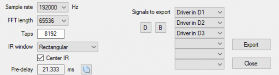
^IR export should be quite okay with your settings, but converting from exported IR back to frequency response could be sensitive to time window and FFT settings. For example here is with ARTA; window start=0, FFT length=8k, win function=Uniform, PreDelay=21.333ms:
Start=0 and PreDelay=21.333ms just to make sure that FFT includes whole IR.
An externally hosted image should be here but it was not working when we last tested it.
Start=0 and PreDelay=21.333ms just to make sure that FFT includes whole IR.
P.S. I would not export IIR XO with Center IR checked due to loss of taps and latency. Short start delay 0.5-1.0 ms is usually adequate for IIR. Linear phase FIR needs centering more often because ca. half of the data could be on the left side of the peak.
Rev. 2.0.38.0 (2020-02-28)
Enclosure
* Added USPL [dB/2.83V/1m] and BL^2/Re calculated fields to driver database.
Enclosure
* Added USPL [dB/2.83V/1m] and BL^2/Re calculated fields to driver database.
Kimmo, thank you very much for to very good software. It would be possible to set the frequency range in Merger and Difraction like in the Calculator?
Thank you
Thank you
Hi kimmosto,
Wrote to the official email address listed in "Help/About" 21 of February 11:11 local, important it wasn't but since it seems i never got a response can i ask was it considered as spam or crap 😀
Wrote to the official email address listed in "Help/About" 21 of February 11:11 local, important it wasn't but since it seems i never got a response can i ask was it considered as spam or crap 😀
..possible to set the frequency range in Merger and Difraction like in the Calculator?
Rev. 2.0.39.0 (2020-03-01)
Main
* Full (5-40k) and standard (20-20k) frequency axis options removed from Options window. Frequency axis limits are adjusted with min. and max. text boxes only. Frequency step changed to one octave. Limits are saved to project file (vxp).
* Angle parsing multiplier saved to project file (vxp).
Enclosure
* Added text boxes for frequency axis limits.
Diffraction
* Added text boxes for frequency axis limits.
Merger
*Added text boxes for frequency axis limits.
...was it considered as spam or crap 😀
I'm just so slow 😀 Thanks for your offer. I think it's better that you archive the data. I can and will ask later if some reference data is needed here.
Rev. 2.0.39.0 (2020-03-01)
Main
* Full (5-40k) and standard (20-20k) frequency axis options removed from Options window. Frequency axis limits are adjusted with min. and max. text boxes only. Frequency step changed to one octave. Limits are saved to project file (vxp).
* Angle parsing multiplier saved to project file (vxp).
Enclosure
* Added text boxes for frequency axis limits.
Diffraction
* Added text boxes for frequency axis limits.
Merger
*Added text boxes for frequency axis limits.
Thank you, its perfect.
Rev. 2.0.40.0 (2020-03-02)
Main
* Responses to off-axis angles defined by user added to Power & DI chart. Visibility of curves is controlled via context menu.
* Show Listening window added to context menu of Power & DI chart.
* User's horizontal and vertical off-axis angles text boxes added to Frequency responses group in Options window. Valid angle list separator is space, comma or semicolon.
Quick change to previous feature for clarity. Sorry about continuous revision spam.
Rev. 2.0.41.0 (2020-03-03)
Main
* Responses to off-axis angles defined by user moved to Directivity chart. Chart type is forced to Line.
Rev. 2.0.41.0 (2020-03-03)
Main
* Responses to off-axis angles defined by user moved to Directivity chart. Chart type is forced to Line.
- Home
- Design & Build
- Software Tools
- VituixCAD