Hi Jack,
Doesn't pressing the F9 function key or clicking the 'Export Data' command button give you what you want?
Kind regards,
David
Hi David:
I'm supposedly a smart guy but sometimes I have blinders on. This time I was in the Transmission Line Loudspeaker Wizard power screen and I wasn't aware of the F9 option or the export button on the memory & width screen. Thought I was on my one because the result was just in the wizard. But I was planning to ask you next. And was right to be cautious because I get different IR result using the F9 export. Thanks for the tip.
Jack
kimmosto, i can not find the post now but i think you said that the edge (baffle simulation software) is not very accurate, especially not when simulating offaxis
On-axis and off-axis within typical listening window are very good as far as I understand. So typical cases for axial simulation and full space to half space conversion work without problems with The Edge.
It's obvious that program is not designed for off-axis simulation because off-axis angle is not user parameter and you cannot simulate shadow sector 90-180 deg. Of course one could hope valid result also with short Mic distance and long X or Y, but the result is not okay. It has full baffle step of 6 dB also close to 90 deg which is not correct. Response to 90 deg should be quite flat with some curves. The same issue exists with some other diffraction simulators such as Bagby's and Laub's Excel sheets. I'm not aware what diffraction model each program uses. Probably 'Bews & Hawsford' is the most popular. That model gives full baffle step to all angles and support ends to 90 deg off-axis.
The Edge, circular baffle dia=340mm, circular driver dia=25mm:
An externally hosted image should be here but it was not working when we last tested it.
VCAD Diffraction uses Distributed Edge Dipole (DED) Model by Urban, Heil, Pignon, Combet and Bauman - with few empirical additions and possible faults 🙂 DED supports also high off-axis angles and shadow sector 90-180 deg. It's simplified and not accurate either, but a step closer to universal approach. Also decades easier and faster to use with off-axis angle parameters.
DED by VCAD: red=0deg, orange=88deg with non-ideal edge, blue=88deg with ideal edge, yellow=180deg
An externally hosted image should be here but it was not working when we last tested it.
thank you very much for your reply!
then the edge looks accurate enough for me, i am most interested in the shape of the frequency ripple offaxis and not so much about correct level 🙂
thanks again!
then the edge looks accurate enough for me, i am most interested in the shape of the frequency ripple offaxis and not so much about correct level 🙂
thanks again!
^Note that also ripple amplitude is too high to off-axis with simulators which are insensitive to off-axis angle. Main problems in off-axis simulation with Edge are horrible user interface, slowness and level normalization by Mic distance which drops response level quite much. E.g. I had to use VCAD Calculator to normalize previous 0 deg and 88 deg curves at 5 Hz to show them in the same graph. But please continue with Edge if self punishment is essential 😉
^Selected variant is with Bold font in the latest build of 2.0.34.0 (2020-01-18)
just saw it, perfect, thank you.
Hello people!
I am fairly new to Vituixcad, but I already love it!
However there is one thing that bothers me and I cannot find the answer in the manual or in here.
Before I learned of VituixCAD I used Rew. I took a measurement importet a curve I created in rephase, adjusted the filter, took a measurement and so on until the drivers response matched the target curve I created in Rephase.
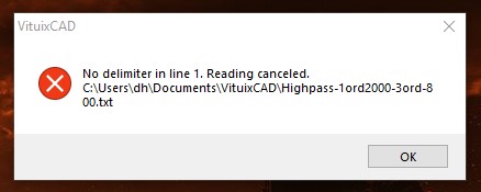
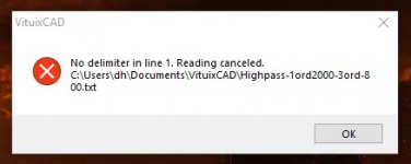
The optimizer in VituixCAD gives the possibility to import a custom axial response target (I want to try something else than the few options provided). But it cannot open the .txt I export from Rephase. I get this error message:
Is it a setting thing in Rephase or are there other reasons?
Thanks!
I am fairly new to Vituixcad, but I already love it!
However there is one thing that bothers me and I cannot find the answer in the manual or in here.
Before I learned of VituixCAD I used Rew. I took a measurement importet a curve I created in rephase, adjusted the filter, took a measurement and so on until the drivers response matched the target curve I created in Rephase.
The optimizer in VituixCAD gives the possibility to import a custom axial response target (I want to try something else than the few options provided). But it cannot open the .txt I export from Rephase. I get this error message:
Is it a setting thing in Rephase or are there other reasons?
Thanks!
Attachments
^Probably the 1st row in response file exported from rePhase does not have legal header line (starts with other than 0-9 or dot or minus) or delimiter (space(s) or tab) is missing between frequency and magnitude values. Comma is not recommended separator character. Phase column is not mandatory, but gives single warning if missing with txt and frd files. Not even warning with cal and mic files.
P.S. I don't understand role of rePhase here. VituixCAD is only program you need in addition to measurement program in case you design XO with VituixCAD.
P.S. I don't understand role of rePhase here. VituixCAD is only program you need in addition to measurement program in case you design XO with VituixCAD.
Kimmosto# Thanks for your reply!
The point of Rephase is for me to generate target curves that are not in the drop down menu of vituixcad, i.e a combination of different filters. This is just for experimental use.
I am not a crossover veteran, so for me to try out new things, I need a target curve to aim for, otherwise I am lost.
It may be because Vituixcad can do it somehow I do not know of.. Rephase may also not be the ideal tool to generate theese curves, but it is the only one I know of.
This is the first line of the generated .txt file:
"0.0000000000109293995860128"
So that should be okay I guess?
^That is impulse response file. External target response must be frequency response file.
Certain target curve of individual driver is not primary design parameter of multi-way speaker so special target curves are quite invaluable. As already told, rePhase does not play any role while designing speaker with VituixCAD.
Certain target curve of individual driver is not primary design parameter of multi-way speaker so special target curves are quite invaluable. As already told, rePhase does not play any role while designing speaker with VituixCAD.
Hello Master Kimmo!
Thank you for your great software!
It's the best software I have seen in a while!
I would consider myself as "power user" (~3 hours per week for the last years).
Just a few small improvement ideas from my side:
1.) "Enclosure" => "Add new driver"/"Edit driver": There should be an Option included to calculate the value for "Rms" automatically, since this value is not given at many driver TSP-sheets. Rms = 2 * Pi * Fs * Mms/Qms /1000 (maybe this function is somewehre I just didn't figure it out yet)
2.) "Crossover"-Modul => element inspector: It would by nice to have a button direct under "Variant" to bypass the single filter or Element.
3.) "Merger": if I load a Frequency-Responce file with a number in the file name, it gives me an error. I think, the programs "thinks" it is an off-axis responce? My workaround: to make a copy of the responce file without any numbers in the name.
4.) Projekt oriented file structure: My biggest fun is to simulate different concepts with virtuixCAD. The folders ("enclosur","diffration",..) get quite crowded and unclear after a while. So I started to create a "project" folder for each new project to save all the files in (at leat diffractions, enclosures and merges). Works good for me, but virtuix Cad does not support this workflow very well.
5.) "Diffraction" => "Export": if "step" and "vertical plane" is activated, there will be ~36 files created for one export. Would it be possible, if "step" is selcted to have another checkbox to automatically create a subfolder? It's just a little bit time consuming to create a subfolder manually each time.
Edit: 6.) "Diffarction" => "View": to position the speakers and microphone easier it would be nice to have a mousewhile-funktion like on the "crossover module" to change the position-value. With this function e.g., it would be easier to find the "best" y-position of a driver wthout changing its x-position.
So, this are just some ideas from my side. Don't know if they make sence to integrate for every user.
Thanks again for the great work!
and kind Regards
Matthias
Last edited:
1.) "Enclosure" => "Add new driver"/"Edit driver": There should be an Option included to calculate the value for "Rms" automatically
Program calculates Rms if you enter value 0. Also Qts, Mms, Cms, BL can be calculated by entering 0.
Re, fs, Qms, Qes, Vas and Sd are required from user.
2.) "Crossover"-Modul => element inspector: It would by nice to have a button direct under "Variant" to bypass the single filter or Element.
Open and Short commands in context menu of schematic are "bypassing" for components and blocks, single or multiple at once. Open, Short and Mute are for drivers.
3.) "Merger": if I load a Frequency-Responce file with a number in the file name, it gives me an error. I think, the programs "thinks" it is an off-axis responce? My workaround: to make a copy of the responce file without any numbers in the name.
Off-axis angle coding in far field measurement filenames is fundamental feature in VituixCAD which overrides everything else. That is really mandatory to enable fast loading of off-axis responses (could be hundreds in a project) so please consider using the program by measurement instructions and user manual.
4.) Projekt oriented file structure: My biggest fun is to simulate different concepts with virtuixCAD. The folders ("enclosur","diffration",..) get quite crowded and unclear after a while.
VituixCAD\Enclosure, .\Calculator, .\Merger folders are just dummy initial values after program installation. Everything including measurements for the project should be saved to VituixCAD\Projects\projectname folder and below it to enable project separation, easy backups and distribution to other users. Recommended directory structure is visible in user manual page 3 (pdf version in English) section "Project directory structure", including example for backup and distribution with 7zip.
5.) "Diffraction" => "Export": if "step" and "vertical plane" is activated, there will be ~36 files created for one export. Would it be possible, if "step" is selcted to have another checkbox to automatically create a subfolder? It's just a little bit time consuming to create a subfolder manually each time.
Probably yes but I don't feel comfortable to create folders automatically after setup.
Edit: 6.) "Diffarction" => "View": to position the speakers and microphone easier it would be nice to have a mousewhile-funktion like on the "crossover module" to change the position-value. With this function e.g., it would be easier to find the "best" y-position of a driver wthout changing its x-position.
Adjusting with Up, Down, Left and Right arrow keys while cursor is at X mm OR Y mm text box enables position adjustment in both axis without moving cursor to different text box (which would be mandatory with mouse wheel).
Hello Kimmo,
you really though about everything! 😉
... and I still need to learn more about your software.
Maybe I should spent a little bit more time with the manual. 🙄
Thanks for your advice!
you really though about everything! 😉
... and I still need to learn more about your software.
Maybe I should spent a little bit more time with the manual. 🙄
Thanks for your advice!
Last edited:
about 1.)that's great! This will save a lot of time in the future! Maybe you can somehow highlight the required values in the parameter form ?
just by making them bolt, or simply add an * after the required parameter?
about 2.) perfect
about 3.) understand
about 4.) thanks, I will check out the manual
about 5.) understand. But maybe there is still a way to make it a bit faster? Maybe at least the naming of the folder?
about 6.) the cursor works great! maybe the mousewheel in addition would be a little bit more intuitive? e.g. select y-position-value by left mouse click, stay with mouse over value, use mouse-wheel to change value.
about 4.) thanks, I will check out the manual
Just for information, obsolete German user manual for version 2.0, and all links to it are now removed.
English version is continuously updated but all small tricks are not necessarily included. For example entering 0 to calculate unknown T/S parameter is not mentioned in user manual.
P.S. Crosscalc checkbox is one option to calculate missing T/S-parameters but is manipulates also existing values if they don't match with overlapping parameters.
Maybe you can somehow highlight the required values in the parameter form ? just by making them bolt, or simply add an * after the required parameter?
Just enter everything you find in datasheet and leave the others 0 and click OK. Program lets you know what are still needed. Usually nothing.
From user manual: "Axial response or input transfer function of driver or output of buffer or total axial SPL or listening window average SPL
can be exported to impulse response in time domain. Typical application is to produce impulse response as wav-file for
speaker controller with DSP FIR support or convolver plugin."
I can't fiqure out how to export .wav/.txt of speaker input (or buffer input) in the program.
Case:
can be exported to impulse response in time domain. Typical application is to produce impulse response as wav-file for
speaker controller with DSP FIR support or convolver plugin."
I can't fiqure out how to export .wav/.txt of speaker input (or buffer input) in the program.
Case:
An externally hosted image should be here but it was not working when we last tested it.
^Click D button to select input of all drivers. Then sample rate of dsp and other settings on the left. See examples below. Taps is number of samples in created IR files. Then click Export, select output file format e.g. 32-bit IEEE mono wav, destination folder and Save. Three files will be created with settings below.

Thanks found it. Total newbie with FIRs. My MiniDSP HD have 1024 taps/channel. I tried 2nd order HP@100Hz. -3 point is where it is supposed to be, but attenuation @20Hz is only -7dB. Not enough of taps?
- Home
- Design & Build
- Software Tools
- VituixCAD