Quick test, I took some compression driver measurement I had. It is 5-20kHz sweep and then copied it and just deleted data and made a comparison.
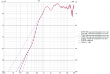
Not sure if the graph is readable, but at least in this case data up to ~250Hz could be truncated without any meaningful change in response. As you see there is some wiggle around ~300-400Hz in the measurement for some reason, not a steady slope, so truncating data there or above the slope would make some error compared to full bandwidth measurement. This doesn't mean my measurement is error free either, so extrapolated response is probably within same error margin as long as truncation is somewhere on the more or less steady natural high pass slope, below drivers' main resonance.
The graph shows that error of extrapolation would be below where the measurement data starts. If this is sufficiently far away from crossover I'd say there is not much of a difference. But, as stated earlier one might as well measure from 5Hz up than rely on extrapolation.
Attachments
Last edited:

Phase response and directivity should be evaluated too when deciding starting frequency. I would use high-passed stimulus with true ribbon tweeters. They are actually fragile and impedance drops very close to 0 Ohms at LF which can be difficult for power amp. Other tweeters can be measured from 5Hz to 41kHz with reduced voltage.
Member
Joined 2003
To be honest I've yet to use a capacitor for measuring a tweeter, but I don't use delicate ribbons. Most tweeters are 90dB+ sensitive, so measuring in-room at say 85dB is well under 1W. For extra protection or piece of mind there is this measurement configuration:VCAD manual for measurement in REW, instructions for Far field measurements;
Range: 5…41000 Hz (full range to avoid extrapolation of response files in VituixCAD)
Does this apply to tweeter as well? Worried about damaging the tweeter with a 5hz signal, so I have measured tweeter with a 500-41000 sweep.
Will this affect any aspect of simulation in VCAD, and if so why?
A wish for future update of Vituixcad; It would be really nice to be able to add a short description to crossover variants. I initially thought the overlay text box could be used for this, but quickly found out that this was not the case.
When I enter a text in the box as shown and switch to variation 2 and then back again to 1,
the text reverts to default.


the text reverts to default.
Member
Joined 2003
The box you are trying to modify is the overlay name suffix...it's for naming overlays, not the crossover variant.
You can put text right on the crossover schematic.

You can put text right on the crossover schematic.
I feel a bit stupid now, I have never noticed that text function! You come to the rescue once again Dcibel, thank you 🙂The box you are trying to modify is the overlay name suffix...it's for naming overlays, not the crossover variant.
You can put text right on the crossover schematic.
BUT, the text box still doesn't seem to save the text even when I add an overlay with the + button.. Maybe I have misunderstood this one as well 🤔
Not a problem as I don't need to save overlays for the moment, but interesting regardless.
Member
Joined 2003
Overlay name suffix does what it says on the tin, it sets the suffix to be applied to newly created overlays. So I enter in some bunk, then create an overlay, and it's name has some bunk at the end. These names are useful when exporting images with legends.

you mean listening speaker not in the box???????Possibly but not necessarily. Wave guide is quite large - possibly too large in many modern speakers though large wave guide might be needed with shoe box enclosure. Equal directivity at XO causes hump to directivity index without significant (~90 deg) phase mismatch.
'As close as possible' could be 'the worst possible' for directivity index i.e. either on axis (~listening window) or power response or both should be compromised to get balanced sound.
Of course if minimal vertical lobing is priority #1 then you should locate as close as possible. Coaxial driver wins that game always, but otherwise not necessarily...probably.
With simplified theory c-c = 1/2 wave length is the worst case for power response with equal DIs, and c-c = wave length at XO is the best case. Simply because sum with difference of 1/2 wave length is null and vertical +/-90 deg have the biggest weight in power calculation (due to dual orbit data to spherical intensity conversion). Early vertical reflections have significance too and DI of different radiators are not always equal => the smoothest DI and ERDI is found when c-c = 1.0-1.4 x wave length. This means that possibility of the worst DI is when c-c = 0.5-0.7 x wave length.
c-c studies are ridiculously easy with VituixCAD. Just load measurement data of the radiators, create ideal flat on axis response (with Optimizer and G(f) blocks) with estimated XO and tune driver's Y mm until combination of DI and ERDI is the best.
Quite many questions and I don't know what "facet" is.
I prefer rounded chamfers, 45 deg and R>=32mm, both quite easy to manufacture. Tweeter should have very small effective baffle size to create directivity above typical XO frequency.
Diffraction tool is limited, but supports designing flat baffle area so that directivity dips and humps due to edges compensate directivity dips and humps of drivers and estimated combination of them assuming phase match at XO. Few tips:
- Do not increase directivity at XO with the box because phase matched XO does it anyway.
- Do not increase directivity below XO with the box because woofer cone does it anyway.
- Increase directivity above XO with the box if tweeter does not have wave guide or wave guide is small.
Member
Joined 2003
I faced the following error message when installing VituixCAD on a Windows 11 machine:
"An error occurred while trying to create a file in the destination directory: The system cannot find the file specified."

It turned out the problem appears due to "Controlled Folders" security setting in Windows 11. Should you face the error above, open Virus & Thread Protection > Virus & threat protection settings > Manage settings > Manage controlled folder access. Disable the Controlled folder access during installation of the VituixCAD.

"An error occurred while trying to create a file in the destination directory: The system cannot find the file specified."
It turned out the problem appears due to "Controlled Folders" security setting in Windows 11. Should you face the error above, open Virus & Thread Protection > Virus & threat protection settings > Manage settings > Manage controlled folder access. Disable the Controlled folder access during installation of the VituixCAD.
I also have Win 11. That setting has probably been Off since the installation because everything has been really smooth. \Users\Public\Documents if free for all users so protection does not look sensible. Whole idea is lost if that folder is locked for single user only or sub-folder creation is prevented.Disable the Controlled folder access during installation of the VituixCAD
2.0.100.1 (2023-03-12)
- Support for Tls 1.1 and Tls 1.2 security protocols enabled to bring auto update and online database in Enclosure tool back to life. Manual download and installation of 2.0.100.1 (2023-03-12) is probably required because my service provider has ended support for Ssl3/Tls1.
Ever since the 2.0.100.1 update with manual installation, Bitdefender has been reporting that Vituixcad files during update installation have flagged for ransomware. While I trust there is no ransomware in the update file, does anyone know why this is happening, and what I can do about it other than telling Bitdefender the files are OK?
Sorry for the newb question but then diffraction tool is only generating angles from +/-90 degree on export. It there a way to increase this to +/-180 degrees?
https://www.diyaudio.com/community/...ith-ideal-drivers.380658/page-15#post-7324509
https://www.diyaudio.com/community/...ith-ideal-drivers.380658/page-15#post-7324509
^Increase axis distance to recommended range; 5000-30000 mm. No sense to simulate directivity to near field (1m) because there won't be realistic baffle loss. Program has simple crash eliminator preventing >90 deg if distance to mic is shorter or equal to longest dimension of the front baffle (from corner to corner).
- Home
- Design & Build
- Software Tools
- VituixCAD