Any chance the 15 filter block limit can be either removed or increased?
Just two numbers in the program, though I'm not 100% sure that everything will work without problems. You can test rev. 1.1.33.0. Block limit is 25 and canvas width 2500px.
Usually "too accurate" EQ to one spot won't pay back. Power response or average to listening window reveals actual need which is typically no more than 8 PEQs.
P.S. Is there a way to donate? VituixCAD is really awesome!
Thanks! Changelog page has donation button with link to paypal.
---
Generally, development of version 1.1 is frozen at the moment. I'm studying possibilities to change network from ladder to free form. Drawing features are quite ready, but I cannot give any promises about schedule and features.
An externally hosted image should be here but it was not working when we last tested it.
Version 2 is quite ready. Systematic testing and few minor features are not done. Installation package is available if someone is interested to play with it: VituixCAD2_setup. This will not override version 1.1, but you need to add separate shortcut for it.
Project file (vxp) format of version 2 is not changing in the future so it's quite safe to save projects and create library blocks. New project files are NOT compatible with older version 1.1. Version 2 does not read project files of version 1.1.
Instructions are not yet available. That may take some time due to summer and other responsibilities.
Drivers tab. It's recommended to add drivers (+) and load frequency and impedance responses before proceeding to Crossover tab. FR smoothing is new feature.
Crossover tab. Rapid guide:
* Drivers in the crossover are linked to the list in Drivers tab by 'Model' name. Driver models are listed in combo box below schematic.
* Zooming in/out is Shift key + mouse wheel. [1:1] button is nominal zoom 10 pixels/snap unit. [Fit] button fits crossover into picture area.
* Components are added by clicking menu button, locating component with mouse and clicking left button. Library blocks (LIB) are selected with open dialog or drag & dropped from file system. Passive components, drivers, grounds and wires can be added with letter keys L,C,R,D,G,W.
* ESC cancels adding and rewinds wiring. Space, Enter or right click accepts/terminates wire.
* Single and multi-selection by clicking or selection window with Shift and Ctrl keys are available. Context menu opens with right click.
* Simple wire stetching is on by default. It's disabled by pressing Alt key while moving components, or using arrow keys (or Cut-Paste).
* Components can be connected to "corners" and ends of the wires. Green highlight indicates valid termination point.
* Red terminal dot of component indicates missing connection. Network solver can handle orphan components but useless trash slows calculation.
* Snap grid and electrical nodes can be shown View->Grid, View->Nodes.
Installer copies 26 library blocks to VituixCAD\Library directory. User can make custom blocks by selecting components and then File->Save Library block. Do not include generator (~) to the blocks.
Parts list is now in data grid and contains new columns such as DCR and wire of coils and Pmax of resistors.
Optimizer hasn't changed much. "Ways" do not exists anymore so you can optimize either total SPL, or single driver's SPL or filter's magnitude response.
Source of Impulse response can be total SPL, or single driver's SPL or filter's transfer function.
Power dissipation of coils' DCR is not yet added. Active blocks prevents output power (and total impedance) calculation because generator is isolated from the load.
Additional tools: Enclosure, Merger, Diffraction, Calculator, SPL Trace and Auxiliary are not changed.
Project file (vxp) format of version 2 is not changing in the future so it's quite safe to save projects and create library blocks. New project files are NOT compatible with older version 1.1. Version 2 does not read project files of version 1.1.
Instructions are not yet available. That may take some time due to summer and other responsibilities.
Drivers tab. It's recommended to add drivers (+) and load frequency and impedance responses before proceeding to Crossover tab. FR smoothing is new feature.
An externally hosted image should be here but it was not working when we last tested it.
Crossover tab. Rapid guide:
* Drivers in the crossover are linked to the list in Drivers tab by 'Model' name. Driver models are listed in combo box below schematic.
* Zooming in/out is Shift key + mouse wheel. [1:1] button is nominal zoom 10 pixels/snap unit. [Fit] button fits crossover into picture area.
* Components are added by clicking menu button, locating component with mouse and clicking left button. Library blocks (LIB) are selected with open dialog or drag & dropped from file system. Passive components, drivers, grounds and wires can be added with letter keys L,C,R,D,G,W.
* ESC cancels adding and rewinds wiring. Space, Enter or right click accepts/terminates wire.
* Single and multi-selection by clicking or selection window with Shift and Ctrl keys are available. Context menu opens with right click.
* Simple wire stetching is on by default. It's disabled by pressing Alt key while moving components, or using arrow keys (or Cut-Paste).
* Components can be connected to "corners" and ends of the wires. Green highlight indicates valid termination point.
* Red terminal dot of component indicates missing connection. Network solver can handle orphan components but useless trash slows calculation.
* Snap grid and electrical nodes can be shown View->Grid, View->Nodes.
An externally hosted image should be here but it was not working when we last tested it.
Installer copies 26 library blocks to VituixCAD\Library directory. User can make custom blocks by selecting components and then File->Save Library block. Do not include generator (~) to the blocks.
An externally hosted image should be here but it was not working when we last tested it.
Parts list is now in data grid and contains new columns such as DCR and wire of coils and Pmax of resistors.
An externally hosted image should be here but it was not working when we last tested it.
Optimizer hasn't changed much. "Ways" do not exists anymore so you can optimize either total SPL, or single driver's SPL or filter's magnitude response.
An externally hosted image should be here but it was not working when we last tested it.
Source of Impulse response can be total SPL, or single driver's SPL or filter's transfer function.
An externally hosted image should be here but it was not working when we last tested it.
Power dissipation of coils' DCR is not yet added. Active blocks prevents output power (and total impedance) calculation because generator is isolated from the load.
An externally hosted image should be here but it was not working when we last tested it.
Additional tools: Enclosure, Merger, Diffraction, Calculator, SPL Trace and Auxiliary are not changed.
Special thanks to bwaslo who sent instructions and source code of XSim3d. Especially filling of sparse matrix with admittances for equation solver would have been mission impossible without good example. C# implementation is quite different but principle is equal.
I don't have any plans to bury version 1.1 though updates may not happen. It will be available for those who don't like or need free form schematic with more than 4 drivers per way. Same story than earlier with LspCAD 5.25 vs. 6.0. Personally I would be happy with simple ladder network but free form offers some valuable features such as:
* Master/room/input EQ common for all output channels. No need to clone or split active blocks to several ways if they should effect to multiple ways.
* Operational amplifiers, though they are turning or already turned to vintage. Not so many (free) simulators with iterating optimizer available for OP amp stages.
* Full support for line arrays etc. without workarounds with groups of 4 drivers.
* Series crossover with more than one driver in parallel.
* Special passive topologies such as Bridged-T, 2nd order all-pass and other complex Lattice networks.
This freedom brings some disadvantages too. For example optimizer is slower to operate because Ways do not exist anymore and cannot be activated/deactivated sequentially. Multi select -> Optimize On/Off in context menu tries to help that issue, but it's not as fast as with Way checkboxes in version 1.1.
I just downloaded and started playing with version 1.1 last night. Looks like I should download version 2 now, before I do too much!
Very nice software! The fact I was able to open it and get my measurements loaded and my actual current crossover implemented and simulated without having to read the manual is fantastic! I will need to read the manual for some of the stuff (having trouble understanding how the targets work) but my first impressions are VERY favourable!
Thank you for making this available to the diy community! 😀
Tony.
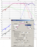
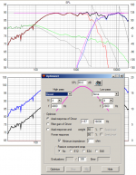
I've been trying to work out the targets. I'm uncertain what I should put in the frequency dialog. When I put in my crossover frequency the curves are way off. Examples attached. target 4th order bessel at 2.8Khz. If I put in 2.0Khz for low pass and 4.0Khz for high pass it appears to be about right.
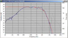
Third attachment is same crossover in speakerworkshop with 4th order bessel target at 2.8Khz.
Is the frequency to put in the corner frequency, rather than the crossover frequency? I'm not even sure how to calculate that! 🙂
Looks like the point release update for V2 fixed the issue of not being able to swap between drivers for the optimizer, so no need to report that 😉
Tony.
Attachments
I just tried to run the optimizer, however it tells me I need to select parameters to optimize, I selected some of the components in the crossover but it didn't help.
Also if I click on a component to change value, the target response disapears from the spl window, it only comes back if I click on the driver. Could it be made to display the target all the time?
Tony.
Also if I click on a component to change value, the target response disapears from the spl window, it only comes back if I click on the driver. Could it be made to display the target all the time?
Tony.
Is the frequency to put in the corner frequency, rather than the crossover frequency? I'm not even sure how to calculate that! 🙂
Unfortunately Bessel filters have (at least) two different designing standards in practice:
a) -3 dB at corner frequency
b) phase shift according filter order at corner frequency
You can select most suitable option for you and possible dsp device with "Bessel phase normalized" setting in Options window. Phase normalized (b) is quite common in dsp devices, though level normalized to -3 dB is more logical for user because level stays constant at corner frequency with any order.
Could it be made to display the target all the time?
Problem is that Optimizer must know what driver is selected for optimizing. If user clicks some other part, optimizer cannot be sure anymore what is the target. Of course we could agree that target driver is the last selected, but user should remember that. Might be difficult if 20 driver instances in the project.
Another implementation option would be listbox of all driver instances. Listbox would refresh automatically if user adds or removes drivers. That would be easiest for the user because target driver selection is maintained while user plays with the crossover. Challenge is that how drivers are identified if there is 20 instances of the same driver in the network. Only choice would Model name + part number which is visible also in the crossover schematic.
I selected some of the components in the crossover but it didn't help.
Turn Optimize bit On. Select components with multi-selection, right click and Optimize On from context menu. Optimize bit must be Off if you want to lock existing value. Optimizer screws up very easily and fast whole network if you forget to switch Optimize Off from all components which are not in the same network with selected target driver.
You can select components from multiple "ways" only for optimizing total axial response.
Another option would be listbox for all driver instances...
This improvement is now done to rev 2.0.0.4, except that driver's consecutive number is not yet shown in schematic. If the same driver exists N times in the network and user is not sure which one will be optimized, he can click correct driver. Much better now, imo.
An externally hosted image should be here but it was not working when we last tested it.
Wow so fast to make a change! 🙂 Thanks for the explanations. My normal approach is to show the target slopes at all times (in speaker workshop it is just an additional curve you add to the graph, and PCD is similar too) and whether I'm using optimiser or just manually tweaking values or trying things I can always see how that affects the match to the target slope. So I guess what I'd like to see is if I have defined target slopes for various drivers (regardless of whether I'm currently trying to optimise them) that there is a toggle to turn those on or off as overlays on the main spl window 🙂
One other thing I couldn't work out how to do (may not be an option) was to add an abitrary overlay in the SPL box. It's useful for sanity checking results, eg an actual measured response compared to the simulated response. It's also useful for checking driver relative offsets if using minimum phase frd's (when you have a measurement of both drivers playing that was taken with the same setup as the individual driver measurements)
I'll try the phase shift option for bessel and see how it looks 🙂
Tony.
nice work on the new version, thanks. The keyboard shortcuts for the main components are a nice touch, a few small UI suggestions if you're taking requests
- when adding a wire, would be nice to be able to click from point to point rather than dragging
- a bulk select for flipping the optimize bit (per component) would be handy (e.g. select n components, check or uncheck the optimise box, applies the change to all selected components), or perhaps adding that to the parts list view might do the job as then you have one dialog that gives you access to all components
- it would be nice to get closer to the old (visual) style of selecting library blocks (e.g.
a popup dialog that lists all the blocks under a button) and/or provide some shortcuts to certain library blocks and/or provide some way to group them by type of component (e.g. LPF, HPF, notch etc)
3ll3dood, I think your second request is already implemented, I "think" I just did it 😉
Kimmosto, changing the bessel option did the trick that is what I was expecting and I'm used to. It may be unconventional for passive crossovers, but is what I have found works well for me 🙂
I tried to download the latest version, but my virus scanner (avast) has quarantined it and sent it off for analysis. They think it is suspicious. I'm sure will get the all clear soon.
Thanks! Tony.
Rev 2.0.0.5
DCR of coils added to Power dissipation graph. Color of resistors is blank (system windowtext) and coils are "Copper Orange" of course.
Driver number added to XO schematic. For example "D1, Audax HM170". The same "D1" can be found in graph tooltips, parts list and optimizer window. This helps identifying if project has several instances of the same driver (with common measurements).
DCR of coils added to Power dissipation graph. Color of resistors is blank (system windowtext) and coils are "Copper Orange" of course.
An externally hosted image should be here but it was not working when we last tested it.
Driver number added to XO schematic. For example "D1, Audax HM170". The same "D1" can be found in graph tooltips, parts list and optimizer window. This helps identifying if project has several instances of the same driver (with common measurements).
I tried to download the latest version,...
Digital signatures for installation packages are not so cheap so I've decided to distribute regular exe which is not so easy to run after downloading. Downloading itself shouldn't be a problem. I've dumped Avast almost a decade ago because it makes life too difficult. Everything is suspicious for it 🙂
I changed the settings to allow me to decide whether to run. Understand about the digital signatures! target curve now stays put! 🙂 thanks!
Tony.
Tony.
- when adding a wire, would be nice to be able to click from point to point rather than dragging
Wiring has been point & click, point & click, ... (not dragging) since the beginning. Maybe I didn't fully understand you message...
- a bulk select for flipping the optimize bit (per component) would be handy (e.g. select n components, check or uncheck the optimise box, applies the change to all selected components), or perhaps adding that to the parts list view might do the job as then you have one dialog that gives you access to all components
Flip/toggle command could in addition to On and Off commands, but that would require status indication in the schematic. Otherwise status of each optimizing bit will be totally lost from user after few toggles with different selection set.
Indication of Opt-bit is coming to schematic very soon. I just need to figure out how to show it. Maybe background color of optimized parameter could be lime or girly pink 🙂
- it would be nice to get closer to the old (visual) style of selecting library blocks
This is good idea, but implementation requires some brain work and time; how to link library file (xml) and image. Primarily I don't like to embed image into xml though it is possible.
- Home
- Design & Build
- Software Tools
- VituixCAD