It's absolutely worth it, because the next thing you be the only software able to model dissimilar drivers in a common enclosure!
😉
😉
No plans to change Enclosure tool to simulate dissimilar drivers in the same system. Measuring effects of dissimilarity requires just calculation.
LspCAD 6 allows simulating dissimilar drivers in shared box, different source impedances, shortcuts, different acoustical loads etc. because also radiator is free-form circuit.
LspCAD 6 allows simulating dissimilar drivers in shared box, different source impedances, shortcuts, different acoustical loads etc. because also radiator is free-form circuit.
2.0.58.5 (2020-12-31)
Power dissipation
* Added 'Export chart data' command to context menu of graph.
No more this year 🙂
Power dissipation
* Added 'Export chart data' command to context menu of graph.
No more this year 🙂
Post carried over from here - Design your own speaker from scratch discussion thread
Yes, eg when I said that DI isn't being referenced to full-space (it should be) - VituixCADkimmosto said:Please let me know in VituixCAD thread
It isn't about errors. I make errors too, and people can work together on that.. it was the rigidity, as well as the unilateral decisions that led me to decide it was untenable, to be continuously auditing VC for suitability.kimmosto said:learning curve
DI isn't being referenced to full-space (it should be)
See changes in rev 2.0.42.0 (2020-03-05):
Unchecking Interpolate and selecting angle step = 0 deg in Options allows using measured angles only for those who don't provide half or full space data.
As mentioned earlier, this action causes errors with rotated or tilted drivers when simulator calculates location geometry because data in two planes only does not support rotation and tilting.
Numerator in DI calculation is power to reference angle (on-axis) or RMS of listening window, and denominator is total intensity. Total intensity covers available data without response or polar pattern extrapolation. Not full space if user is not able or willing to provide it as response data.
About accuracy, current situation of DI calculation with full space data in 1-2 planes:
omni, angle step 5 deg = 0.000 dB
cardioid, angle step 5 deg = 4.772 dB
cardioid, angle step 10 deg = 4.774 dB
cardioid, angle step 15 deg = 4.775 dB
cardioid, angle step 20 deg = 4.778 dB
cardioid, angle step 30 deg = 4.785 dB
dipole, angle step 5 deg = 4.771 dB
super-cardioid, angle step 5 deg = 5.716 dB
hyper-cardioid, angle step 5 deg = 6.022 dB
So possible problems are coverage and accuracy of measurement data in addition to mathematical rotation from two planes only to simulated directions in 3D space. This applies to simulation phase. Final QC measurements of complete speaker should be done at far field so whole construction locates in single point X,Y,Z=0,0,0 -> response timing, interpolation and rotation is not happening in the program.
That is unfortunate, and incorrect. Thank you for your time.Not full space if user is not able or willing to provide it as response data.
^For example wall mounted half space constructions are possible to measure to half space only. No pressure to rear sector means that rear sector does not have any effect to shape of DI and power responses. Therefore also scaling to full space e.g. adding +3.01 dB offset would be artificial and unnecessary. It will not give anything valuable for the designer.
Same story with corner speakers pressurizing quarter space in horizontal plane and half space in vertical plane. That is the sector which affects to shape of power and DI so directions through the walls are insignificant. Main problem at the moment is that VCAD does not support quarter space in horizontal while half space in vertical with response mirroring and angle interpolation which are very valuable in practice speeding up measurements. Not much problem to add but why to add for a single user other than me.
Same story with corner speakers pressurizing quarter space in horizontal plane and half space in vertical plane. That is the sector which affects to shape of power and DI so directions through the walls are insignificant. Main problem at the moment is that VCAD does not support quarter space in horizontal while half space in vertical with response mirroring and angle interpolation which are very valuable in practice speeding up measurements. Not much problem to add but why to add for a single user other than me.
Last edited:
^As already said, that is just constant scaling which does not change anything else that mixes chart graphically by lifting DI curves over the other curves and dropping power curve too low without any meaning/advantage for the designer or speaker itself. Even more important in practice is that program cannot not know whether user loads partial response data measured from full space design or full data measured from quarter (or half) space design. Safest and simplest is to calculate with loaded data as is without assumptions by user - no matter final location or acoustic design.
2.0.59.0 (2021-01-03)
Main
* Added Corner checkbox to Options window. Includes hor -45...+45 deg and ver -90...+90 deg in power & DI calculation and directivity chart.
Main
* Added Corner checkbox to Options window. Includes hor -45...+45 deg and ver -90...+90 deg in power & DI calculation and directivity chart.
Let's test this. The latest build of 2.0.59.0 (2021-01-03):
* 3.01 dB added to DI when Half space is checked in Options.
* 6.02 dB added to DI when Corner is checked in Options.
All DI curves (DI, ERDI, ERDIhor, ERDIver) are lifted if Half space or Corner is checked, but mostly at LF so graphical disadvantage is acceptable imo.
DI values are too low if response data does not include selected radiation space.
If both are unchecked, all four DI curves are calculated by loaded angles only i.e. without constant offset assuming that speaker radiates to full space. DI values are too low if response data does not include full 0-180 deg for full space calculation.
Shape of DI responses is not changed so this is mostly academic which does not affect to design.
Note also that all radiators in the system use the same radiation space set in Options so e.g. sub cannot be Half space or Corner while main speakers are full. Advantage is that DI curve does not have incorrect step from sub to mains due to change in offset.
Last edited:
VituixCAD_help_20.chm (windows help) and pdf replaced with VituixCAD_help_20.html with external png images.
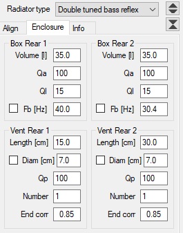
for the closed box enclosure tab, is it possible to get the qtc and fc information visible at all times, like below the fb [hz] info?
Today I've completed the assembly of a Najda DSP and a 6x180W hypex amplifier.
I'm asking myself which DSP system I should use in VituixCAD options ?
Nicolas (WAF audio), sadly is missing since 2019, and I don't know how to find the answer. If it can help, I think that the DSP board use a dual-core DSP56725.
I don't recall Nicolas ever declaring what filter definitions or biquad formats he had designed Najda to. I had some success using "The Active Crossover Designer" (ACD) spreadsheet from Charlie Laub, which was made for miniDSP, but the problem I had at the time was that filter shapes on the high frequency end were inaccurate. I tried to engage him on this, but I failed get him to address the issue. So, I think you are on your own here when it comes to selecting which DSP option to choose (I am personally interested in knowing the answer).
I'm just following up on this query. I'm not sure if it provides any answers, but I did discover new (to me) information relating to biquad coefficients on page 14 of the Najda_Under_Control_Manual.pdf here: https://web.archive.org/web/20160315195113/http://waf-audio.com/doc/Najda/Najda_Under_Control_Manual.pdf
for the closed box enclosure tab, is it possible to get the qtc and fc information visible at all times, like below the fb [hz] info?
Box groups were designed for worst case scenarios such as passive radiator and double tuned reflex so there's no extra space without changing group size on the fly.
Tooltip of Volume text box shows continuously fb and Qtc of closed detected from simulated impedance curve. Hopefully adequate enough?
I have tried to organize and simplify documents.
Software page is just feature list. Installation, how to start working and links to videos and forums are moved to user manual to keep this page as simple as possible and avoid duplicate information and work.
User manual is html document. The same html file with png images is source, online and local distributed inside setup.exe. pdf, chm (local win help) and source docx are removed.
Measurement instructions are still pdf.
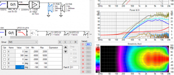
I have tryed a sim with 4 and 8 ohms, the phillips speakers have not a good filter.
What I did see is that the frequency is not doubled in 4 or 8 ohms, but the parts is doubled when I do both 4 and 8 ohms.
system has 1 % Chebyshev not the best filer. see the 3 way plot, missing part in mid, or maybe it is on purpose because ears are sensitive in that area and give speakers this way a warmer sound as Phillips alwys did, but missing detail.
regards
Attachments
Last edited:
Hi Kimmosto:
I am modeling a .75" x 30" ribbon as a stack of 42 18x18mm (or 21 18x36) rectangular diaphragms. No matter what I do, it gives me an axial DIP of about 6 db and 10 degrees wide. I find the existence of such a dip hard to believe as it would have shown up in ribbon measurements by this time but I can't find anything I'm doing wrong. If you would be kind enough to take a look, I expect you will spot the problem in a minute.
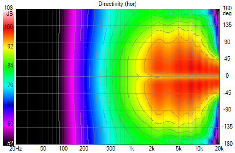
I called it an on axis DIP but it could also be a calculation artifact. The reference angle SPL is 6 db lower than other angles which look like what one would expect from having imported them into REW. When I compute directivity in 10 deg steps the dip is 20 degrees wide; with 5 degree directivity its 10 degrees wide. In other words, only the 0 degree SPL line is anomalous.
Thanks for your help,
Jack
I am modeling a .75" x 30" ribbon as a stack of 42 18x18mm (or 21 18x36) rectangular diaphragms. No matter what I do, it gives me an axial DIP of about 6 db and 10 degrees wide. I find the existence of such a dip hard to believe as it would have shown up in ribbon measurements by this time but I can't find anything I'm doing wrong. If you would be kind enough to take a look, I expect you will spot the problem in a minute.
I called it an on axis DIP but it could also be a calculation artifact. The reference angle SPL is 6 db lower than other angles which look like what one would expect from having imported them into REW. When I compute directivity in 10 deg steps the dip is 20 degrees wide; with 5 degree directivity its 10 degrees wide. In other words, only the 0 degree SPL line is anomalous.
Thanks for your help,
Jack
Attachments

^Simulation has two separate HF radiators with c-c distance of 2x388 mm. Separate radiators need tilting of atan(388/2000)=11 degrees towards virtual microphone to get flat axial, assuming listening distance of 2000 mm in Options. Lower driver T=+11 deg (up) and upper driver T=-11 deg (down).
I guess you have generated responses with Diffraction tool. Root problem is that Diffraction tool calculated individual small radiators to infinity so you need to generate single long radiator instead of two shorter.
I guess you have generated responses with Diffraction tool. Root problem is that Diffraction tool calculated individual small radiators to infinity so you need to generate single long radiator instead of two shorter.
Attachments
- Home
- Design & Build
- Software Tools
- VituixCAD