Thanks! There might be possibility to fill in the data with Python script, haven't given closer look yet.
Not always so, sometimes only one is right.An easy to work with baffle would be one which will work for a variety of crossover frequencies.
Things tend to change when diffraction gets involved. Generating a minimum phase plot from magnitude is a risk and should only be done if you're messing around, say with factory data.I would have guessed that you could estimate the phase based on the magnitude,
Last edited:
Is this confirmed to be the GOOD PRACTICE?I have confirmed this. There are two ways to get the same answer in simulation.
(1) hold the virtual mic in a constant position in the diffraction tool, and collect the diffraction responses from the drivers. Then when modeling the crossover filters, keep the driver coordinates at 0,0,0.
(2) position the mic on each drivers axis in the diffraction tool and collect the diffraction responses from the drivers. Then when modeling the crossover filters, enter the correct driver coordinates.
Based on reviewing some of Kimmo's past writings, I think he would prefer us to use (2). But both methods generate the same result.
Unfortunately, I did it wrong on some of these ideal-driver studies.
Easy to make a mistake here with big influences.
What I did is, in the diffraction tool put the mic in the listening position (my case tweeter axis) and leave it there. Then take the responses for each driver in their right position.
But also changed the Y and Z position in the XO design.
Seems wrong ..... :-(
How about the DISTANCE AXIS? Some seem to put in 1 meter some 2, 3 , 4m .... It also has a big influence....
(2) position the mic on each drivers axis in the diffraction tool and collect the diffraction responses from the drivers. Then when modeling the crossover filters, enter the correct driver coordinates.
This is the preferred way. The fact that it works the other way (in this idealized situation) simply indicates that the software is mathematically consistent.
In any normal simulation, using measured responses, the designer will need to provide the x, y, and z coordinates anyway. If the virtual mic position is held constant on the tweeter axis, it complicates how the x,y,z coordinates would need to be entered. It is a completely unnecessary complication, because Kimmo has designed the software to use x,y,z locations properly with the virtual mic position. Within the software, the virtual mic position is different than the virtual listening position.
I have been going over my past work. When I have been using measured driver responses, I have been doing the process correct. But when doing simulations with idealized driver responses or OEM traced responses, I have been doing it wrong. It usually changes the simulation by a small amount, and I have not found a case where it makes a dramatic difference... still, it is embarrassing.
Live and learn... Jim
Nothing is embarrassing if you learn from the mistakes.This is the preferred way. The fact that it works the other way (in this idealized situation) simply indicates that the software is mathematically consistent.
In any normal simulation, using measured responses, the designer will need to provide the x, y, and z coordinates anyway. If the virtual mic position is held constant on the tweeter axis, it complicates how the x,y,z coordinates would need to be entered. It is a completely unnecessary complication, because Kimmo has designed the software to use x,y,z locations properly with the virtual mic position. Within the software, the virtual mic position is different than the virtual listening position.
I have been going over my past work. When I have been using measured driver responses, I have been doing the process correct. But when doing simulations with idealized driver responses or OEM traced responses, I have been doing it wrong. It usually changes the simulation by a small amount, and I have not found a case where it makes a dramatic difference... still, it is embarrassing.
Live and learn... Jim
To be honest...blushing... can you rephrase the mic position part? I read it several times but get distracted with virtual and stuff 😛
And the axis distance? Thank for the effort
Distance from transducer to mic is included in the measurement data (as long as same windowing is used across measurements). If you do "measurements" with the diffraction tool, you can set the distance there. If all transducers are on same plane and mic was held same distance from the plane, then there is no need to change Z coordinates for any driver.
If mic is on axis of transducer while taking measurements, like recommended, then in the main program one has to use the coordinate system of drivers to "position" the drivers (measurements) as they are in reality on the baffle. This positioning with coordinates is relative to rotation axis and chosen design axis, which can be anything, the listening height. Basically you pick one point on the baffle as your reference point in simulator, against which you would calculate (or tape measure) all the coordinates for the drivers (use center of drivers, the mic position while making measurements, normal to the plane).
If you have chosen design axis between tweeter and mid for example, and both drivers have their centers aligned on same vertical line (x coordinate), then only thing you do is set your tweeter Y to some positive value, for example 30mm, and woofer value to negative, for example -100mm. Given that you moved the mic on axis of each driver when taking the measurements.
If the baffle has steps on it, or some other weird stuff is going on, and you measured constant distance between mic to driver, then you would need to input the z coordinate for example. Or, if your tweeter was on the baffle corner and woofer on the middle, then you'd have to use x-coordinate for the tweeter perhaps. If your woofer is on the side of the box, then use the R -rotation of the measurements or T if the woofer was on top of the system pointing up. Usually all the rest can be left 0 and only the Y coordinate needs to be adjusted, when all transducers are on same baffle and on same vertical (rotation) axis.
When this is set like so the program is able to figure out distances and angles to listening position (toe-in / design axis included) and show the combined response there, at listening position. Advantage of this is that you can now adjust the coordinates if you wish to try and see if some other driver positioning worked a bit better. Or, if you wish to see how the speaker works if it is high above the listening height for example, or rearrange the drivers upside down, or how the simple room boundaries affect. There might be many other things, I don't know the actual reason why Kimmosto determined this is the best way to do things. It gives most flexibility with least error I think. Measurements are simple and the simulator setup is simple. The system can be used anyway designer wants though, the responsibility is with the user.
If you don't need this kind of flexibility, you could keep your mic static while measuring all transducers and save some time on the measurements (then leave all coordinates 0, measurement data includes driver positions relative to each other already). There is going to be some error, which is fine as long as you know that there is some error magnitude of it 🙂 As Hifijim said it is not too much. Especially if small speaker in question, in relation to listening distance. Like small bookshelf speakers. Quick check on right angle triangle calculator says 10cm off at 3 meters is only ~2 degrees and 2mm too far, no biggie for end result.
Last edited:
I disagree with you.The fact that it works the other way (in this idealized situation) simply indicates that the software is mathematically consistent.
Kimmo always recommends measurement, and so do I. You shouldn't be getting the same result from these two methods.
AllenB et al., this thread's topic is "with ideal drivers" !
Let's not distract this case with instructions and practises that are applicapble to real world non-ideal drivers!
Let's not distract this case with instructions and practises that are applicapble to real world non-ideal drivers!
I was talking about baffle geometry and simulation methods. The drivers have nothing to do with it per se.
Posted some ideal driver sims here https://www.diyaudio.com/community/...to-one-forum-member-an-ob.374532/post-6889630 . Attempt was to see if a real world speaker and it's crossover tuning and resulting "perceived sound quality increase" had something to do with vertical early reflections. Of course there is no conclusion if it has or not, but it looks like there is less interference at listening spot from the early reflections (mainly floor reflection) after tuning the crossover, which might be at least part of the reason sound quality was perceived better.
Interesting bit on this is that it kind of relates to Kimmosto 1.4wl c-c stuff. kstrain observation for sound quality is that sound is better with new xo frequency whose c-c is below 1wl (~450Hz) than with original xo c-c around 1.4wl (~700Hz). I think this complements Kimmosto "rule", which was associated with tweeter xo, octave or more up in frequency. To me this seems to relate to wavelengths in comparison to typical room /listening situation, where relatively long wavelengths ( < 1kHz) can yield very wide dips in frequency response due to interference from early reflections all starting up rather close to each other (slightly different path length through each boundary) so Kimmosto rule is not significant in comparison with the resulting huge dips in listening spot frequency response. On higher frequencies it looks like psycho acoustic smoothing renders the dips non existent indicating hearing system is not perceiving the resulting interference as frequency response at least which could explain it is important to have similar sound from the reflections as the direct sound for ear to ignore the reflections or something, ease out the computing process. This is what Kimmosto original 1.4wl c-c "rule" aims at, similar response through tweeter crossover towards vertical early reflections as direct sound.
I don't know about time domain and what is perceived better in which situation, haven't done own listening tests and haven't read scientific studies on this. This is why I did the test, try and figure out what features on the VCAD graphs might correlate to perceived sound quality, since this is not clear to me at least.
Nevertheless, something with ideal drivers 🙂
Last edited:
Some background information, sims and observations about the direct + early reflections seen in the in-room estimate graph on another thread: https://www.diyaudio.com/community/threads/a-3-way-design-study.376620/post-6847168 See the next post as well, Fluid posted some references from Toole and his own observations. Actually my VCAD sim pollution seems to start from post #229 https://www.diyaudio.com/community/threads/a-3-way-design-study.376620/post-6845416 . Not with ideal drivers but could be 🙂 These provide background for the latest experiment in previous post so in that sense relevant here.
Last edited:
Kimmosto's suggestion was based strictly on the resulting impact on CTA 2034 score as far as I know. Which is a fantastic place to start, but we can't forget it's a limited model, not the full reality. I would prefer a smooth and reduced vertical reflection. For example, Erin's Audio Corner Klippel test of the Perlisten demonstrates where my thinking has evolved the last few years.
You are right, the CTA 2034 doesn't show reality. I'm trying to figure out if and how the in-room estimate available in VCAD, with simple one corner first reflection ability, is something that translates to perceived sound quality and could provide some more info for designers. Is it something that could be useful while designing speaker system and how to interpret it, how it translates to perceived sound quality. It shows interference of direct sound and first reflection(s) at listening position, but nothing else. Even if all CTA 2034 metrics were optimal, DI and ERDI and what not, the in-room estimate changes as the speaker is positioned and moved in room (simple corner in this case). There might be octave wide many decibel dip below 1kHz, or if the system is juggled a bit the in-room estimate can be very nice in comparison, while the CTA 2034 metrics stay pretty much the same on both cases.
Ever wondered why many high-end speakers are quite tall and have one or more mid drivers above tweeter? Might be just business related, but it seems tallness shows in the in-room estimate as well, through the early vertical reflections (with some non OB speakers I've played with, see links in previous post). kstrain speaker seems to have the mid quite high as well and in his case the system physical setup is able to get rid of the first vertical reflection related interference dips on in-room estimate, a configuration that has bettered perceived sound as well. Very interesting 🙂 Vertical reflections are very interesting since they depend on room height and listening distance, which is pretty much the same for most, around 2.5m, for majority of people living in standard sized housing. Rather independent of other speaker positioning "issues", people seem to put the speakers where they fit. There might be "ideal height" for mid transducers in this regard and to me it seems it is not between floor and listening height like all speakers sold (and DIYed) in quantities are set up.
Ever wondered why many high-end speakers are quite tall and have one or more mid drivers above tweeter? Might be just business related, but it seems tallness shows in the in-room estimate as well, through the early vertical reflections (with some non OB speakers I've played with, see links in previous post). kstrain speaker seems to have the mid quite high as well and in his case the system physical setup is able to get rid of the first vertical reflection related interference dips on in-room estimate, a configuration that has bettered perceived sound as well. Very interesting 🙂 Vertical reflections are very interesting since they depend on room height and listening distance, which is pretty much the same for most, around 2.5m, for majority of people living in standard sized housing. Rather independent of other speaker positioning "issues", people seem to put the speakers where they fit. There might be "ideal height" for mid transducers in this regard and to me it seems it is not between floor and listening height like all speakers sold (and DIYed) in quantities are set up.
Last edited:
AllenB – perhaps I have not been clear in what I have been saying. I am talking about the very specific case where the VituixCad diffraction tool is used to generate a “pseudo virtual” measurement which is then used in the main crossover tool.
On the other hand, AllenB, most of the time when you tell me I have made a mistake, I have in fact made a mistake. So perhaps I am missing the big picture.
I will make three posts which show my evidence which convinced me that Tmuikku (post 47) and David Morison (post 43) are correct.
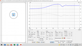
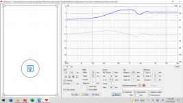
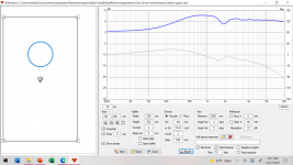
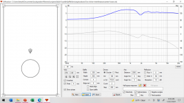
I have modelled a 500mm x 300mm baffle with a pair of drivers vertically arranged. The design axis is centered between the two drivers. The drivers are hypothetical cones with Sd=100 cm^2 and are arranged 200 mm apart. A correct simulation should show strong cancellation nulls in the vertical plane, but not the horizontal plane.
The first example, we do it the preferred way: Using the diffraction tool, we simulate a measurement of the upper and lower drivers by positioning the virtual mic on each driver’s axis. Then in the main crossover tool, we input the y-coordinates to space the drivers 200 mm apart. The upper driver is +100 mm, the lower driver is -100 mm.
On the other hand, AllenB, most of the time when you tell me I have made a mistake, I have in fact made a mistake. So perhaps I am missing the big picture.
I will make three posts which show my evidence which convinced me that Tmuikku (post 47) and David Morison (post 43) are correct.
I have modelled a 500mm x 300mm baffle with a pair of drivers vertically arranged. The design axis is centered between the two drivers. The drivers are hypothetical cones with Sd=100 cm^2 and are arranged 200 mm apart. A correct simulation should show strong cancellation nulls in the vertical plane, but not the horizontal plane.
The first example, we do it the preferred way: Using the diffraction tool, we simulate a measurement of the upper and lower drivers by positioning the virtual mic on each driver’s axis. Then in the main crossover tool, we input the y-coordinates to space the drivers 200 mm apart. The upper driver is +100 mm, the lower driver is -100 mm.
Attachments
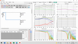
Next I will show the results of using a non-standard technique. I will hold the virtual mic in a constant position in the diffraction tool, and I will collect the diffraction responses from the drivers. Then when modeling the crossover filters, keep the driver coordinates at 0,0,0.
You can see that I get the same vertical response pattern as above, except for very high frequencies as we would expect.
Just to be clear, this is NOT the recommended process for using VituixCad diffraction tool... But the fact that it does give the same response pattern shows that the tool is versatile enough to handle this situation.
Attachments
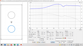
Here is a sim which really surprised me. Here I simulated BOTH drivers in the diffraction tool, and exported the response to the main crossover tool... Then in the crossover tool I model the response as if it came from a single driver, in other words, a single loudspeaker system. Once again, VituixCad shows how versatile it is and gives the correct response.
Attachments
The third one is expected in this specific circumstance.
Take the second and the first. It kind of looks like vc has made the connection that the two separate baffle sims are part of the same overall speaker. I wouldn't have expected that and it looks to me that while you have clearly made the connection, you weren't initially expecting that either.
So where does that leave us? If you were to experiment with modifying the distance between the drivers via the Y axis in the crossover tool, does it actually change, or does it take this diffraction simulated response from the old distance and superimpose it with the new, creating a hybrid, or does it do something else?
If this were perfectly explained then there is no problem. Otherwise there will be uncertainty in the result.
I tried many things and got different result. Because I don't have the knowledge I don't know which one is the right one.The third one is expected in this specific circumstance.
Take the second and the first. It kind of looks like vc has made the connection that the two separate baffle sims are part of the same overall speaker. I wouldn't have expected that and it looks to me that while you have clearly made the connection, you weren't initially expecting that either.
So where does that leave us? If you were to experiment with modifying the distance between the drivers via the Y axis in the crossover tool, does it actually change, or does it take this diffraction simulated response from the old distance and superimpose it with the new, creating a hybrid, or does it do something else?
If this were perfectly explained then there is no problem. Otherwise there will be uncertainty in the result.
Very frustrated and pity because it is a powerful tool.
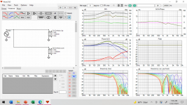
I want to add one more variable. There is also an enclosure tool. How do you use this one together with the driver/XO and diffraction tool?
That is the right order to use those?
That are the right parameters to use in each?
The manual isn't clear.
A practical example would help a lot.
Take the second and the first. It kind of looks like vc has made the connection that the two separate baffle sims are part of the same overall speaker. I wouldn't have expected that and it looks to me that while you have clearly made the connection, you weren't initially expecting that either.
I don't really know what I was expecting, since I got it wrong, and have been doing it wrong for several months. I don't understand how I got confused. When using a real mic in a real room, I followed the process correctly, but I had a blind spot when using the virtual mic in the diffraction tool. It seems so obvious in hindsight.
- Home
- Loudspeakers
- Multi-Way
- VituixCad Simulations with Ideal Drivers