A Hilbert transform or other method for generating a minimum phase response from a magnitude only curve is a reasonable way to go. I haven't worked out yet if it is just a data to plot issue or if the simulation borks the phase in some way for some reason. My main interest has been in looking at the directivity which isn't affected so I have put zero effort into working out why so far.Understood... and if phase is useless, the VituixCad simulation will not be valid. I would have guessed that you could estimate the phase based on the magnitude, using Hilbert... but honestly, I know so little about waveguide simulation I am just guessing.
YesIn your opinion, is it possible to create hypothetical waveguide tweeter simulation?
No to this part. If the tweeter to be used is fixed a waveguide can be designed for it. Some waveguides work out OK on a number of tweeters. A simulation could be made for a waveguide like a WG148 and a tweeter that is known to work well with it. This is about as generic as you could get.One that would be useful, and reasonably representative of waveguide tweeters in general?
At lower frequencies lots of methods for making things generic work out to be very similar to the real thing. Once the frequency gets high, very small deviations to the dome, surround and face plate can have quite an impact.
If you are interested in direct radiating mainly, scanspeak has 3D models of all their drivers on their website and it should be quite possible to make a reasonably accurate half space simulation of specific tweeters. It would take some effort though and at this point in time I really shouldn't divert myself from trying to get my CNC working. If there was to be agreement on one specific model or the SB26A was acceptable the effort would be significantly reduced. I am already too easily distracted by new shiny threads that come along 🙂
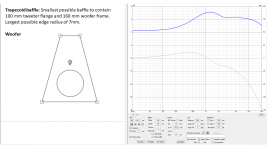
This next simulation is an example of making the baffle as small as possible. I am once again assuming that the tweeter we like has a 100 mm flange (very common), and our 6 inch driver has a 160 mm frame size. I want to stick with shapes that a reasonable craftsmen could make from sheet stock in a home workshop, without needing a CNC machine. So a trapezoid shape seems the most straightforward way to get the baffle as small as possible.
The baffle in this simulation is just big enough to encompass a 100 mm flange tweeter and a 160 mm frame midwoofer. There was just enough space left on the sides that I could accommodate a small roundover (or bevel) of 7 mm.
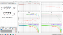
As we can see, the tweeter response is rather ragged, and I was skeptical that this sim could be salvaged. This is a result of an almost hard edge... 7 mm radius is not much, and we clearly get a lot of diffraction off that hard edge so close to the tweeter... The fact that the sides and top are nearly equidistant to the tweeter does not help at all. However, the final result was not too bad, and I was a little surprised at how well it turned out.
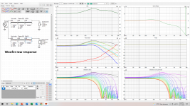
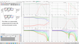
The best filter I could come up with uses a 3rd order on the mid-woofer, and a 4th order on the tweeter. At first I had the woofer filter modelled as a 1st order and a 2nd order cascaded, this providing me with a lot of flexibility... but a simple 3rd order BW ended up doing just fine.
Comparing this to the first sim in post #3, I conclude there was no advantage, in this particular case, of making the baffle as small as possible. This particular trapezoid shape did not seem to have any advantage over a rectangular shape, and the very small edge radius was a notable issue.
j
The baffle in this simulation is just big enough to encompass a 100 mm flange tweeter and a 160 mm frame midwoofer. There was just enough space left on the sides that I could accommodate a small roundover (or bevel) of 7 mm.
As we can see, the tweeter response is rather ragged, and I was skeptical that this sim could be salvaged. This is a result of an almost hard edge... 7 mm radius is not much, and we clearly get a lot of diffraction off that hard edge so close to the tweeter... The fact that the sides and top are nearly equidistant to the tweeter does not help at all. However, the final result was not too bad, and I was a little surprised at how well it turned out.
The best filter I could come up with uses a 3rd order on the mid-woofer, and a 4th order on the tweeter. At first I had the woofer filter modelled as a 1st order and a 2nd order cascaded, this providing me with a lot of flexibility... but a simple 3rd order BW ended up doing just fine.
Comparing this to the first sim in post #3, I conclude there was no advantage, in this particular case, of making the baffle as small as possible. This particular trapezoid shape did not seem to have any advantage over a rectangular shape, and the very small edge radius was a notable issue.
j
Attachments

Re your use of the Y coordinate for vertical height in the main window, isn't this already baked into your sims from the common mic position in the baffle diffraction window?
Thanks,
David.
Thanks,
David.
David,
diffraction tool and crossover simulator are two separate steps. Hence, setting a driver position in diffraction tool is creating the the acoustic diffraction only, of a driver with a given Sd and position on a baffle. This is not about driver summation, but governs the radiation behaviour of the radiator. You would still need to tell crossover simulator to calculate the drivers at the given distance to one another to sum accurately.
diffraction tool and crossover simulator are two separate steps. Hence, setting a driver position in diffraction tool is creating the the acoustic diffraction only, of a driver with a given Sd and position on a baffle. This is not about driver summation, but governs the radiation behaviour of the radiator. You would still need to tell crossover simulator to calculate the drivers at the given distance to one another to sum accurately.
Just an observation, but it seems your tweeter and woofer are pretty far apart. Horizontally that won't be a problem, but how about it's vertical dispersion.This next simulation is an example of making the baffle as small as possible. I am once again assuming that the tweeter we like has a 100 mm flange (very common), and our 6 inch driver has a 160 mm frame size. I want to stick with shapes that a reasonable craftsmen could make from sheet stock in a home workshop, without needing a CNC machine. So a trapezoid shape seems the most straightforward way to get the baffle as small as possible.
The baffle in this simulation is just big enough to encompass a 100 mm flange tweeter and a 160 mm frame midwoofer. There was just enough space left on the sides that I could accommodate a small roundover (or bevel) of 7 mm.
As we can see, the tweeter response is rather ragged, and I was skeptical that this sim could be salvaged. This is a result of an almost hard edge... 7 mm radius is not much, and we clearly get a lot of diffraction off that hard edge so close to the tweeter... The fact that the sides and top are nearly equidistant to the tweeter does not help at all. However, the final result was not too bad, and I was a little surprised at how well it turned out.
The best filter I could come up with uses a 3rd order on the mid-woofer, and a 4th order on the tweeter. At first I had the woofer filter modelled as a 1st order and a 2nd order cascaded, this providing me with a lot of flexibility... but a simple 3rd order BW ended up doing just fine.
Comparing this to the first sim in post #3, I conclude there was no advantage, in this particular case, of making the baffle as small as possible. This particular trapezoid shape did not seem to have any advantage over a rectangular shape, and the very small edge radius was a notable issue.
j
If this is a deliberate choice could you shine some light on that? I would expect they could be placed way closer together, even with a 100 mm flange.
Just an observation, but it seems your tweeter and woofer are pretty far apart.
I think it is an optical illusion. In the diffraction model, the tweeter diaphragm is 30mm diameter and the woofer is 123 mm effective diameter. However, the tweeter flange is 100 mm and the woofer frame is 160 mm. This means the closest they can be is (100+160)/2=130 mm. This is what I modeled, with perhaps an extra 5 or 10 mm of space for practical purposes.
Correct, if mic and DUT stays still, then one should not set driver coordinates in main window.Re your use of the Y coordinate for vertical height in the main window, isn't this already baked into your sims from the common mic position in the baffle diffraction window?
Thanks,
David.
Recommended procedure for measurements is that each driver is measured microphone in front of thst particular driver, DUT or mic is moved to achieve this. Then Y coordinates are set according to design axis. If design axis is tweeter, then tweeter coordinates are left 0 and woofer gets ~-130mm in hifijims example case. If design axis was between the drivers, then maybe - 80mm for woofer and 50mm for tweeter.
This enables playing around with Y (x and Z as well) offset in the crossover window in order to see if some other driver layout worked better.
I think mic should be moved in the diffraction simulator as well, to keep results and prosedures consistent. This allows to play with c-c, flip the whole thing upside down, raise the whole system in terms of room etc. Just many more variables to play with and experiment on.
Correct, if mic and DUT stays still, then one should not set driver coordinates in main window.
Thanks, that was what I was expecting.
Recommended procedure for measurements is that each driver is measured microphone in front of thst particular driver, DUT or mic is moved to achieve this. Then Y coordinates are set according to design axis. If design axis is tweeter, then tweeter coordinates are left 0 and woofer gets ~-130mm in hifijims example case. If design axis was between the drivers, then maybe - 80mm for woofer and 50mm for tweeter.
Yes, I agree if we're using real measurements then starting each one on axis to the driver and accounting for the offset in main crossover window is good.
I think mic should be moved in the diffraction simulator as well, to keep results and prosedures consistent.
Good, idea, I hadn't thought of doing it that way round, thanks.
I think the diffraction tool mimics the recommended measurement prosedure and generates files like real measurements, except the measurement distance can be the default 3m without worrying about reflections like with home measurement setup 😀 And it is not 3D model of the speaker, only ideal baffle, flat disk as driver etc., cannot replace real measurements. I might be wrong, but this is how I think about and use the tool.
I had thought that it worked as Sheeple said in post #44. However, I just did an experiment simulation of two drivers on an IB and confirmed that it actually works the way Dave Morison and Tmuikku describe it. I need to re-simulate the diffraction responses by moving the microphone to be on-axis for each driver.
well sh!t ... !!! 😡
well sh!t ... !!! 😡
There was a very similar question asked in the Vituix thread that started here and in the posts below. I can see why there are two ways to look at this.
https://www.diyaudio.com/community/threads/vituixcad.307910/post-6720445
To get a definitive answer it might be worth asking kimmo directly over at the HTG thread.
http://www.htguide.com/forum/showthread.php?44128-VituixCAD-v2
https://www.diyaudio.com/community/threads/vituixcad.307910/post-6720445
To get a definitive answer it might be worth asking kimmo directly over at the HTG thread.
http://www.htguide.com/forum/showthread.php?44128-VituixCAD-v2
Thank you for starting this excellent discussion!It was suggested that we needed a new thread where people could post their VituixCad simulations to enhance the general knowledge of cabinet diffraction issues and baffle layout.
j.
😮‼️ This suggests John K. with his NaO Note II RS, S. Linkwitz with his LX521 & Jorma Salmi with the Gradient speakers all were on to something long ago. Those minimal baffle designs did not feature, in general, rebated drivers nor rounded baffle edges.if the baffle is minimized the bulk of the diffraction is removed
The directivity of the LX521 and Note II being dipole over a large range also contributes as they effectively have 90 degree front radiation much like a waveguide helps reduce the effects of edge diffraction.This suggests John K. with his NaO Note II RS, S. Linkwitz with his LX521 & Jorma Salmi with the Gradient speakers all were on to something long ago. Those minimal baffle designs did not feature, in general, rebated drivers nor rounded baffle edges.
I think they all suggest crossing dipole drivers below the dipole peak, which I think they refer as peak caused by ideal dipole, since it is practically same as main diffraction hump with open baffle or boxed speakers and I would call it just diffraction peak 😀 But I only know what I saw in simulator, not much theoretical background on any poles.
Same trick can be used for boxed speakers as well, crossover below diffraction interference to another way. It just makes more ways to the system, which adds cost and complexity but gets rid most of diffraction. Still, there would be case with the tweeter, which you cannot crossover to another way above anymore, but for tweeter one can use very good waveguide, wink wink.
As sidenote I think open baffle speakers have worse diffraction interference, since the back wave diffracts too. At the baffle edge, the backwave has inverse polarity and diffracts around the edge towards listening position. This sums constructively with the front wave edge diffraction created secondary sound source, which is also inverse polarity towards listening position, making the effect worse. I think this was explained on some other thread but too tired to search for it now. The effect is seen in VCAD diffraction tool as well, the hump gets bigger and dip deeper when you engage "Open baffle" checkbox.
Here ideal monopole, dipole and some emulated cardioidish patterns cycle in single GIF animation, all with (practically) same size baffle and transducer. All of them have diffraction hump and dip after it.
Attachments
Last edited:
I think the diffraction tool mimics the recommended measurement prosedure and generates files like real measurements, except the measurement distance can be the default 3m without worrying about reflections like with home measurement setup 😀 And it is not 3D model of the speaker, only ideal baffle, flat disk as driver etc., cannot replace real measurements. I might be wrong, but this is how I think about and use the tool.
I have confirmed this. There are two ways to get the same answer in simulation.
(1) hold the virtual mic in a constant position in the diffraction tool, and collect the diffraction responses from the drivers. Then when modeling the crossover filters, keep the driver coordinates at 0,0,0.
(2) position the mic on each drivers axis in the diffraction tool and collect the diffraction responses from the drivers. Then when modeling the crossover filters, enter the correct driver coordinates.
Based on reviewing some of Kimmo's past writings, I think he would prefer us to use (2). But both methods generate the same result.
Unfortunately, I did it wrong on some of these ideal-driver studies.
I think the second option is recommended because it allows some experiments with less error than the first method. It lets the simulator calculate response at angles. If baffle is small and two way speaker, there should be too much error for small adjustments either way I think. Didn't check though. I trust Kimmosto has put lot of thought on the procedure initially and hasn't changed his mind later on makes the second option the most accurate one for most work. First option would save some time and perhaps even increase accuracy on some small speakers measurements ( because DUT or the mic won't be touched between measurements other than the rotation of the DUT ). For diffraction tool either could work, as long as the user knows what he is looking at 🙂
Posted simple experiment few minutes ago on another thread, where I used ideal driver and copy of it to approximate interference pattern with reflection through desk. The application is speakers for computer desk and near field listening and question was to try and minimize effect of the desk reflection.
The experiment doesn't give what is good system for the application or how to fabricate one, or which drivers to use. Experiment was really fast and simple way to see what kind of problems there is with the reflection through the desk and what is required from a speaker system which tries to address the interference. At what bandwidth interference happens and how much attenuation towards reflection zone would be needed to reduce interference to negligible levels gives some hint what kind of system would be required to really address the problem. But it leaves the designer to determine what is the problem, and how to utilize the information, and what extend one should go with it etc. Anyway, I think very helpful tool to help thinking a system.
https://www.diyaudio.com/community/...field-pc-monitoring-setup.380734/post-6882866
Last edited:
Would you share the script?Vituix doesn't natively simulate waveguides but the data from other programs or measurements can be imported and added in to an overall simulation.
For example this ABEC simulation shown in VACS can be exported as text and imported into Vituix. I made a script for renaming the files to the Vituix naming convention to automate the procedure. It's not perfect and I have never worked out why the phase is all wrong (probably my fault) but the magnitude works very well.
I have before here are the posts with the scripts inWould you share the script?
https://www.diyaudio.com/community/...-wall-or-corner-placement.337956/post-6568215
https://www.diyaudio.com/community/...-design-the-easy-way-ath4.338806/post-6800791
I don't think the phase from ABEC is going to work directly unless the full frequency range with rolloff's is simulated. It is possible to generate useful minimum phase data for the truncated frequency data in REW by using the add HF and LF tail options as shown in the attached image. Doing this for each response would be quite tedious. Without it the generated minim phase is nonsense because of the truncated range.I got this working as well few days ago, responses from ABEC to VCAD, and was about to ask what is wrong with the phase 😀 There is some weird peaks going on in the phase data. I'm gonna look into this some day
Attachments

- Home
- Loudspeakers
- Multi-Way
- VituixCad Simulations with Ideal Drivers