Be it in US or Europe, the ground symbol you see on schematics is a conceptual 0V potential reference.
This 0V potential is connected to the chassis for shielding purposes and this has not necessarily to be done in only one point.
A good wiring of a circuit usually tries to make different points where the 0V reference is necessary (or at least, some of them where it is very crucial) to have the smallest differences of potential between them.
Then the importance of supplying the lowest impedance to the ground path(s).
The usual, unexplained, "rules" of star wiring and avoiding ground loops are of recipes essence. They are of no help to understand what is really needed to be achieved.
.
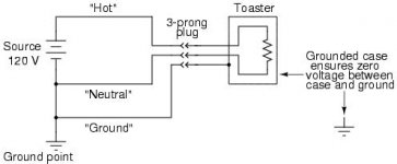
One last time, if it connects to a building's electrical system ground, then it's a bonding connection. If it doesn't, then it's not.
Or put another way, anything that connects to the third prong is a bond. Anything that doesn't, isn't.
Admittedly that's a pretty complicated definition, and might take some study to grasp. But I have to admit that my own ability to explain yes-or-no is now exhausted, so maybe some references will aid in further study.
Electrical bonding - Wikipedia, the free encyclopedia
https://www.google.com/webhp?complete=0&gws_rd=ssl#complete=0&q=bonding+connection
https://www.google.com/webhp?complete=0&gws_rd=ssl#complete=0&q=bonding+connector
Wishing you much comprehension.
.
Attachments

.
Actually wait a minute, there might be something here worth saying.
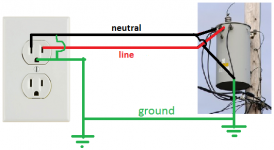
In the illustration, notice that neutral and ground are connected together. This occurs inside the breaker/fuse panel, it's not normally visible.
Since they're connected together, it's possible to have the impression that the neutral and ground are electrically the same, so either-which doesn't matter.
But no, it very much matters because of the hot feed. Notice that the hot wire feeds the neutral (so to speak), but has no connection to the ground wire.
The result is that neutral (white in the USA) is termed current-carrying, and can be a lethal hazard. Speaking only in the context of electronics, current flows in other devices can create noise and distortion.
In contrast, the ground conductor (green/bare) never carries current--or something's broken if it does--and is the universal zero.
While as before, any connection to the zero-voltage, zero-current ground conductor is correctly termed a "bond," he added in a resigned sort of way.
.
Actually wait a minute, there might be something here worth saying.
In the illustration, notice that neutral and ground are connected together. This occurs inside the breaker/fuse panel, it's not normally visible.
Since they're connected together, it's possible to have the impression that the neutral and ground are electrically the same, so either-which doesn't matter.
But no, it very much matters because of the hot feed. Notice that the hot wire feeds the neutral (so to speak), but has no connection to the ground wire.
The result is that neutral (white in the USA) is termed current-carrying, and can be a lethal hazard. Speaking only in the context of electronics, current flows in other devices can create noise and distortion.
In contrast, the ground conductor (green/bare) never carries current--or something's broken if it does--and is the universal zero.
While as before, any connection to the zero-voltage, zero-current ground conductor is correctly termed a "bond," he added in a resigned sort of way.
.
Attachments

Last edited:
I thought the question was where to connect a virtual ground to a LM3886 chipamp.com kit.
Chipamp.com have designed a pcb with a ground plane that has connections for PSU grounds, speaker ground and chassis ground (CHG). It was designed that way! There is a small trace connecting the input/feedback ground and the ground plane. It was not designed for Protective Earth duty.
Bentsnake, I can't follow your logic any more.
The ground conductor is a bond? The neutral and ground are connected and not bonded?
Last edited:
I thought the question was where to connect a virtual ground to a LM3886 chipamp.com kit.
...the question I asked was NOT how to design a virtual ground or which design to use, but HOW/WHERE to connect it both to the chassis and to the specific chipamp.com board. ...Now at this point all the "grounds" are accounted for, but NOTHING is connected to the chassis or EARTH. Where/how do I do that?
PS it's not an LM3886, it's a Cmoy.
.
Last edited:
I am also using a virtual ground, but on a much larger scale in an effort to 'rehab' a dynaco ST-120. (I also did one using 'updatemy dynaco' circuits, but for this one, I want to use chipamp.com's LM3886 boards,
post #4
Last edited:
I thought the question was where to connect a virtual ground to a LM3886 chipamp.com kit.
Chipamp.com have designed a pcb with a ground plane that has connections for PSU grounds, speaker ground and chassis ground (CHG). It was designed that way! There is a small trace connecting the input/feedback ground and the ground plane.
WOW. If I had looked more closely at the pcb and seen the spot labeled "CHG" I could have avoided the last 3 pages of exchange - but think of all the fun we would have missed! 😀
Perhaps my situation is unique, but the results were so dramatic that I feel I should share them. First, my power supply is a virtual ground design created with two high power resistors and two 10kuF capacitors in a voltage splitter configuration followed by zener controlled MOSFET voltage regulators. I used ChipAmp.com boards. I created a star ground with leads from the virtual ground on the power supply and the Chassis Ground location on each board. My input jacks were grounded to the chassis.Not insulating the input sockets may lower the overall impedance of the ground track and makes the circuit more silent than otherwise.
When I first powered it up, all was well and it was dead silent. I connected it to a preamp and got horrendous hum! There was even hum when the preamp was connected but off! Now both this amp and the preamp are old style with only two prong plugs. Reversing the plugs had no effect on the hum. Floating the input sockets removed all hum. I don't have a good explanation, but in this case grounding the input sockets, CREATED hum, not removed it. Your mileage may vary.
.
One last time, if it connects to a building's electrical system ground, then it's a bonding connection. If it doesn't, then it's not.
Or put another way, anything that connects to the third prong is a bond. Anything that doesn't, isn't.
Admittedly that's a pretty complicated definition, and might take some study to grasp. But I have to admit that my own ability to explain yes-or-no is now exhausted, so maybe some references will aid in further study.
Electrical bonding - Wikipedia, the free encyclopedia
https://www.google.com/webhp?complete=0&gws_rd=ssl#complete=0&q=bonding+connection
https://www.google.com/webhp?complete=0&gws_rd=ssl#complete=0&q=bonding+connector
Wishing you much comprehension.
.
There might some confusion between 'ground' and 'earth'
Ground does not mean the ground, it's earth that is connected to the earth
I've redrawn this from "Tangent Soft's" TLE2426 based virtual earth supply to take both 2 x 9v batteries in series and a 24v dc supply. I've incorporated a SPDT on-off-on switch to do this, thus avoiding using diodes in it's path.
I may have overlooked something! Can anyone spot anything missing or not right with this? Would this work?
Thanks
I may have overlooked something! Can anyone spot anything missing or not right with this? Would this work?
Thanks
Attachments
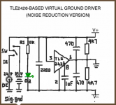
Basically OK.
Theoretical rather than real practical issues might be the LED having obviously different brightness levels on the two voltages (use a current source or sink to eliminate that). Depending on the switch used it might be worth adding a limiter resistor to the supply exiting the switch to prevent arcing from abruptly trying to change the voltage across a 2200uf + 2 series 470uf caps.
Theoretical rather than real practical issues might be the LED having obviously different brightness levels on the two voltages (use a current source or sink to eliminate that). Depending on the switch used it might be worth adding a limiter resistor to the supply exiting the switch to prevent arcing from abruptly trying to change the voltage across a 2200uf + 2 series 470uf caps.
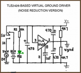
The sig gnd label is in the wrong place.
Those two grounds are Power Grounds.
Your signal ground will come from the mid point between the +V and -V at the output of your opamp.
Change that 3bar label to virtual gnd.
Those two grounds are Power Grounds.
Your signal ground will come from the mid point between the +V and -V at the output of your opamp.
Change that 3bar label to virtual gnd.
Mooly, thanks for the tip. I don't really mind different brightness, since the battery/dc voltages too are different at 18v & 24v respectively. I'm a bit lost on your suggestion, how do I connect it and what value should that be?
Thank you AndrewT for pointing this out, an oversight on my part!
I wonder if the 2200uF cap is an overkill? Can I use, say a 220uF/470uF cap instead? What's the significance of using very high value caps on charging & discharging?
Is there any way of increasing the current capability on this yet avoiding another TLE 2426?
Thanks guys.
2200uf probably is overkill, certainly for battery use anyway. On mains and a lot depends on how clean the incoming supply is. The CMOY draws so little current that a series resistor of say 22 ohms might be beneficial. You could add that to the incoming 24 volt feed.
Modern LED's are very bright on currents of only a few hundred microamps so I would suggest first seeing what current suits the brightness you are after. Use your resistor initially to find out.
A constant current source (or sink) can be just a single FET wired like this. RL would be replaced by the LED. The resistor RS would be determined experimentally to set the current (brightness) and that would then be essentially unchanging with supply voltage. Something like a J111 or J112 FET should be suitable.
Attachments

I'll then use a smaller cap instead. As for using an FET, I'll wire it up as it is & see how it works before attempting this.
Thanks
Thanks
The ground conductor is a bond? The neutral and ground are connected and not bonded?
Old question, but important to understand.
The ground is only for conducting a ground fault current. Without it, a fault current could be conducted to ground through a user of the device. In the old days, sometimes you would get a shock from the refrigerator. With a three wire (grounded) plug, this is much less likely. If all loads are operating correctly, there will be zero current through the ground wire.
The neutral is known as the designated conductor and conducts all currents to ground under normal operating conditions. Although nominally at zero volts reference, there can be a voltage on the neutral conductor and it can be a dangerous/fatal voltage if there is a high resistance junction or wiring fault. This is just one reason why you shouldn't play around with the house wiring unless you know exactly what you're doing. Just turning off the circuit you're working on can be very dangerous if there's another circuit using that neutral, because if you start disconnecting the neutral there can be full voltage on one of the neutral wires in the box. This was the very first hard knocks lesson I learned working as an electrician. I thought I was so smart and then ZAP from the neutral wire. Also, the neutral wire is not protected by a fuse, so if you wire the circuits wrong you can overload it. An open neutral is far more dangerous than an open hot.
The ground and neutral are bonded together inside the service panel. This is the only place they should be connected together.
Moral of the story: Don't mess with the house wiring unless you know exactly what you're doing. It is deceptively simple and many, many "electricians" really screw it up. I have a callous on my forehead from facepalming when I open the service panel and see the creative (dangerous) wiring inside. Just because it works doesn't mean it's safe. Keep your hands out of there! Leave it to a pro.
I have scars from burns, damage to my retinas from a flashover arc in my face, and damage to my corneas from white hot shrapnel exploding out of a service box. Be smarter than me.
https://www.youtube.com/watch?v=rdQR7-Ap6YQ
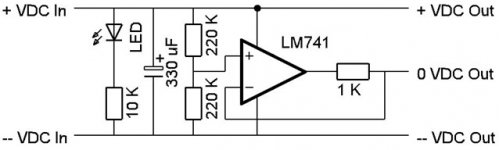
You can use opamps for rail splitters (the 1k will seriously limit how much current can sourced/sunk from the opamp) but opamps have limitations on minimum supply voltage and current delivery. You would be lucky to get more than around 18ma from a 741. I think the short circuit current is around 25ma. Some devices might object to the rail capacitance (that is seen as a load) and try and oscillate even though the capacitance is try to kill it. Done correctly its a workable solution though.
- Status
- Not open for further replies.
- Home
- Amplifiers
- Chip Amps
- Virtual ground in Cmoy amp