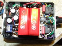
I finally managed to assemble and test the H.phone amp. The TLE 2426 blew up on the initial power up since the DC socket was wired incorrectly as shown in post 59! After rewiring the DC socket correctly and with a new TLE chip it worked very nicely with the +/- voltages at 12.03/12.04 respectively. There was hardly any dc offset on the ic outputs either!
It was surprisingly very quiet and worked well with both the batteries and the smps, albeit a little less bass. The head phones may have also played a part in this due to their fairly high impedance(s)
I wonder if I could either add another TLE2426 across v.e supply to increase the current capacity or use a BUF634 at the output?
The op amp i'm using is an OPA2132.
Thanks
Attachments
Last edited:
I've never heard of paralleling the virtual ground generator.
The definitive test is whether or not you are experiencing clipping/distortion when driving the intended load. If you are then you might need to look at a combination of things. Using higher impedance headphones should be a warning that you may need higher supply voltages rather than more current delivery.
The definitive test is whether or not you are experiencing clipping/distortion when driving the intended load. If you are then you might need to look at a combination of things. Using higher impedance headphones should be a warning that you may need higher supply voltages rather than more current delivery.
I've never heard of paralleling the virtual ground generator. Using higher impedance headphones should be a warning that you may need higher supply voltages rather than more current delivery.
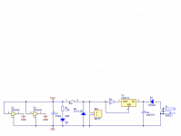
The attachment below is for a v.earth/charger circuit for another Cmoy h.phone amp, which prompted me to explore the possibility of connecting 2 x TLE2426!
Well, this unit isn't meant to drive h.phones over 16-32 ohms given the constrains of it's design.
Attachments
No doubt it would 'work' although both devices would need to be identically matched.
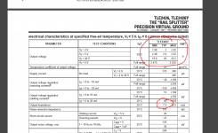
If you measure the voltage from -Vcc to gnd you should find it approximately equal to one of the supply voltage. If each device has a slightly different output voltage, and each device has a low output impedance (which I assume it has as that is the whole point of the thing), then the devices will 'fight' each other with one trying to force current into or out of the other.
If you measure the voltage from -Vcc to gnd you should find it approximately equal to one of the supply voltage. If each device has a slightly different output voltage, and each device has a low output impedance (which I assume it has as that is the whole point of the thing), then the devices will 'fight' each other with one trying to force current into or out of the other.
Lets put some numbers in.
The data sheets shows typical values for output voltage. Worst case you could have 0.4 volts difference between two devices at 40 volts. On 18 volts lets be generous and say they are within 100 mv of each other.
The output impedance is given as being 7.5 milliohms.
How much current would try and flow between the two devices ? I=V/R = 0.1/0.0075 which is 13 amps. So the devices would just current limit and devour your batteries by fighting amongst themselves.
Attachments
No doubt it would 'work' although both devices would need to be identically matched.
If you measure the voltage from -Vcc to gnd you should find it approximately equal to one of the supply voltage. If each device has a slightly different output voltage, and each device has a low output impedance (which I assume it has as that is the whole point of the thing), then the devices will 'fight' each other with one trying to force current into or out of the other.
From your last post...."How much current would try and flow between the two devices ? I=V/R = 0.1/0.0075 which is 13 amps. So the devices would just current limit and devour your batteries by fighting amongst themselves. post
Thank you for pointing these as I didn't realize this w.r.t connecting 2 TLE 2426 in parallel! I'm not sure how this circuit was implemented in that Cmoy design! As for draining the batteries, I intend using a SPDT switch to select between these two voltage sources, so I hope this scenario doesn't arise!
I just connected the circuit to my laptop h.phone out and it sounded extremely clear and loud even after I reduced the feedback resistor from 10k to 4.7k! Incidently, I used a Sennheiser HD202 which has an impedance of 24ohm.
Good to hear its all sounding OK.
The switch should be fine although I wouldn't like to say that the changeover would be silent.
The switch should be fine although I wouldn't like to say that the changeover would be silent.
Thanks to you Mooly for your invaluable tips & guidance in no small measure, it works beyond my expectations within it's design constraints. I tried a few JFets, along with NE5532, & LM4562 but settled on OPA2132 since this sounded the best to my ears! Drives low Z h-phones, especially the Sennheiser HD202/24ohm quite well with adequate bass too.
Well, I haven't yet tested the switch for that "thump" since I have always had this habit of turning down the volume on any thing I used!
As for using 2 TLE2426 in parallel, I think i'll leave it in this as it is, but now planning on making a guitar/bass H.Phone amp using an OPA552 with it's 200mA output current!
- Status
- Not open for further replies.
- Home
- Amplifiers
- Chip Amps
- Virtual ground in Cmoy amp