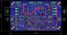
Hello Hugh, I am using this version of bandol layout. Both the trimmers are placed side by side in this layout.
thanks
thanks
Attachments
Last edited:
Are you using the schema from https://www.diyaudio.com/forums/sol...mplimentary-mosfet-amplifier-post5552827.html
If so, VR2 should be the bias pot and value of 1k was recommended as a correction on the BOM.
If so, VR2 should be the bias pot and value of 1k was recommended as a correction on the BOM.
Are you using the schema from Very simple quasi complimentary MOSFET amplifier
If so, VR2 should be the bias pot and value of 1k was recommended as a correction on the BOM.
Yes thats the one I am using and you are correct I have used 1K from the latest BOM with the correct trimmer value.
Thanks
Hi manniraj,
Sorry for the late response but I am in holidays in Mauricius and I have no access to my files! Hopefully l have seen that Hugh and avtech23 answered your question 🙂
I will be back next week...
Rgds,
Marc
Sorry for the late response but I am in holidays in Mauricius and I have no access to my files! Hopefully l have seen that Hugh and avtech23 answered your question 🙂
I will be back next week...
Rgds,
Marc
Thank you Marc, lucky fellow......!!
VR1 is the offset.
VR2 is the bias (the pot which sits across the BD139 Vbe bias generator).
That is all you need.......
As AV23 mentions, 500R may be insufficient for range, 1K permits you to bring down the bias current to much lower values. However, around 125mA is correct as we mentioned across the RCR 0.33R resistor (45mV).
Hugh
Hugh
Thank you Marc, lucky fellow......!!
VR1 is the offset.
VR2 is the bias (the pot which sits across the BD139 Vbe bias generator).
That is all you need.......
As AV23 mentions, 500R may be insufficient for range, 1K permits you to bring down the bias current to much lower values. However, around 125mA is correct as we mentioned across the RCR 0.33R resistor (45mV).
Hugh
Hugh
Thanks Hugh, yes VR2 is for the bias and I could dial it to 45mV across one of the 0.33R resistor using extended pins underneath the board to test the voltage. The offset is damn good on both the boards with drifting between -0.2mV - 5mV. Pretty surprised that without any changes to the VR1 the offset is so good on both the amp boards 🙂
But the bias is not stable sometimes drifting downwards or upwards of 45mV even after running it for more than an hour. Does my heat sinks not sufficient as they run quite hot after an hour with 45mV bias? I thought bandol was running his with smaller heat sinks than mine. Yet to hear the amp will set the bias/offset again and hear the music by tomorrow.
Offset is not tightly controlled on this amplifier and the reason many users like a servo.
A servo is NOT needed however.
Wait until the amp is warmed up, half an hour idling, then set the offset to 0mV -/+15mV. It will move up and down regularly according to thermal effects.
Furthermore, the bias (quiescent) is dynamic and will change a little. Set it up warm, half an hour after idling, and accept that it will go up and down a little. Be sure that the Vbe multiplier, the BD139, is in thermal contact with one of the output devices. These changes are normal, transistors are extremely sensitive to temperature effects, but as it warms up the quiescent should drop a little. This is intended to cool off the amp should it become very hot under heavy use.
Congratulations, you have a new amplifier to test now!
Cheers,
Hugh
Last edited:
Wait until the amp is warmed up, half an hour idling, then set the offset to 0mV -/+15mV. It will move up and down regularly according to thermal effects.
Be sure that the Vbe multiplier, the BD139, is in thermal contact with one of the output devices. These changes are normal, transistors are extremely sensitive to temperature effects, but as it warms up the quiescent should drop a little. This is intended to cool off the amp should it become very hot under heavy use.
Hugh
I did not get what you meant by thermal contact of BD139 with the output devices? Right now I have mounted the BD139 beside the mosfet output device on the heat sinks. But using a thermal insulation pad with slight amount of thermal paste. Yes you are right regarding the temperature increases/decreases the bias also changes a bit drifting along. But I could set the bias to around 45mV (usually what I can get best is around +/-5mv after warm up for 30 mins and resetting it back). There is output ground, so what I have done is use couple of wires on one of the heat sink mounting holes to take as grounds for both the channel outputs to my speaker protection boards. As bandol suggested I have connected the both PSU output grounds together. But do you want me to take this PSU ground where I have joined to the chassis ground the same place where I have connected the safety ground from IEC to the chassis?
Thanks
No, your system will be fine. But the big question is this:
'Do you have any hum or intrusive noise?'
Of course, you will have to connect your speakers to find this. Then, your most sensitive measurement, your ears, will tell you the truth.
If yes, you have some work to do with the earthing system. Otherwise, you are fine.
Hugh
'Do you have any hum or intrusive noise?'
Of course, you will have to connect your speakers to find this. Then, your most sensitive measurement, your ears, will tell you the truth.
If yes, you have some work to do with the earthing system. Otherwise, you are fine.
Hugh
Hello Hugh,
Finally I am back from holidays 🙁 Thank you for taking care of the support during my trip 🙂
While I was on the beach with nothing to do, I had a question in my mind about the Quasi (that is very good by the way and I still need to make some more listening test now that I have more time...) :
- Why we are using a MOSFET instead of two NPN bipolar transistors like the 2SC5200 or the NJW3281 for the output stage ?
Thanks for advise and best regards,
Marc
Hi Marc,
Welcome back from the Maldives!! A fascinating country with difficult politics which is slowly slipping into the ocean.......
You go to the core of the design.
An engineer designs an amp for lowest THD.
But THD is an aggregation - a sum - of ALL the harmonics in the distortion.
Some distortions, however, sound very good, like second harmonic. A few do not like this, however, but generally in the minority.
So I like to define which distortion is good (musical harmonics) and bad (electronic distortions which are objectionable, such as H5, H6 and pretty high higher orders).
Conclusion: If THD is inevitable, it is best to remove as much H5 and beyond harmonics as we can whilst leaving, or even enhancing, H2 and H3 and maybe H4 too. With maths, it is possible to simulate which part of the THD is given to H2, H3 and H4. If that figure is over 99%, then the objectional harmonics might be 1% of the total THD. This could - and for me generally works - gives us measure of quality of a SS amplifier.
Even order harmonic is created by asymmetrical distortions on the full waveform. That is, if we look at the CRO, the top of the wave may be wide, and the bottom of the wave may be narrow. That generally describes H2 and some H4. There will many harmonics in all the distortions analysis, and by M. Fourier (your math guy, thank you for him!) we can assemble a train of harmonics on LTSpice showing all the harmonics.
What makes high levels of H2?
Well, a big difference in transconductance between top and bottom outputs of a PP amplifier.
If the mosfet is at the top, and bipolar at the bottom, the differences in gm are huge. Actually, since the upper and lower devices are used in different ways (upper is source follower, and bottom is common emitter) this gm difference is always 'built in', so H2 and H4 are enhanced anyway. More differences with difference devices, mosfet and npn, bring out this gm difference even more.
This creates the H2 and H4 you hear in the Quasi, which is sweet, and rich.
You hear the subliminal, psychomotor sounds of distortion. These are very low; H2 is around -45dB in a tube, but in the VSQ it's at -70dB, but the ear responds with 'warm'.
This is my conclusion of 25 years designing amps but I have to tell you that a number of significant designers disagree very strongly with these ideas. That's good; progress is created by unreasonable people........... even if they are wrong, they highlight concepts which are understood in the conventional body of work.
Ciao,
Hugh
Last edited:
Hi Hugh,
Thanks for your detailed answer 🙂 I will think about it for my next hybrid project...
By the way, I was not in the Maldives but in Mauritius near Madagascar 😉
Cheers,
Marc
Thanks for your detailed answer 🙂 I will think about it for my next hybrid project...
By the way, I was not in the Maldives but in Mauritius near Madagascar 😉
Cheers,
Marc
By the way, I was not in the Maldives but in Mauritius near Madagascar 😉
Cheers,
Marc
Hi Marc,
good choice for vacation, excellent beaches, Pamplemousses Botanical Garden, colored earth, the mountain Le Morne Brabant in fog and mystic Ile aux Cerfs. A real fine location to relax.
Cheers
Günni
PS: Me also wanna go back there
Hi Günni,
Yes, it is a nice place and people are very friendly, but the Island has been too much developed 😡
I was there several times about 25 years ago and I really enjoy it, but now the business with tourist has badly damaged some places like the Isle aux Cerfs, where there is no more Cerf, but a lot of (too much) tourist boats and commercial outlets, restaurant, tourist shop, attraction places, etc...
Only the Pamplemousse Botanic Garden didn't change a lot 🙂 but plenty of mosquito
Hopefully our Hotel in the North was very nice and we had much less rain than in the center of the Island like in Curepipe 🙂
Best regards,
Marc
Hi Hugh,
No problem, it is also an Island 😀
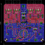
Back to the hybrid amplifier, can I ask you what do you think about the project I am working on ? I have been using very common MOSFET that I had in stock. I also added an on board solid state relay protection based on the project16 design that I have used in the Quasi. I had to play a little with the CAD software to squeeze everything on a board of less than 10 cm to get a low price from PCBWay 😉
I think that the tube stage could increase H2 distortion which is good for the musicality of the amplifier based on your previous comment ! The tube will work best as a voltage amplifier while the MOSFET will be far better than tube for current amplifier and they will not require an expensive and heavy output transformer 🙂
Cheers,
Marc
No problem, it is also an Island 😀
Back to the hybrid amplifier, can I ask you what do you think about the project I am working on ? I have been using very common MOSFET that I had in stock. I also added an on board solid state relay protection based on the project16 design that I have used in the Quasi. I had to play a little with the CAD software to squeeze everything on a board of less than 10 cm to get a low price from PCBWay 😉
I think that the tube stage could increase H2 distortion which is good for the musicality of the amplifier based on your previous comment ! The tube will work best as a voltage amplifier while the MOSFET will be far better than tube for current amplifier and they will not require an expensive and heavy output transformer 🙂
Cheers,
Marc
Attachments
Marc,
Your circuit is good and will work well. I'm attracted to hybrid amps, but they are difficult to do correctly.
What tube is used here? I'm guessing a 12AU7? If so I would see OLG of around 16x18=288, and CLG of (4k7+0k15)/0k15 = 32, so global fb as you have it arranged would be around 288/32=8.9 which is around 19dB. This is a very low global fb and it would sound very good.
You do not have the two triodes in open loop; they are within the fb loop which inserts into the cathode of V1A. Your Zout is very low because it's taken off the mosfet Q1; good move as it will be the tens of ohms. Huge drive to the output stage, important during the crossover transitions.
Excellent choice of hexfets here; easy to drive and strong output at even low frequency.
I do not think I would have changed any of your parameters. Is this circuit? It's very good........
Cheers,
Hugh
Hi Hugh,
I am happy that you like the design because I am not an expert and I make project based on a lot of reading from other people 🙂
Yes you are right the tube is a 12AU7 or ECC82 as we call it in Europe but your question remind me that I had good experience with the Russian 6N1P therefor I have added a jumper to use both tubes in this amplifier...
If there is no other possible improvement, I will send the files to PCBWay to produce it, and I will start a new thread to stop to monopolise the Quasi thread 😎
Best regards,
Marc
Attachments
- Home
- Amplifiers
- Solid State
- Very simple quasi complimentary MOSFET amplifier