Thanks Marc, will use 1N4007 ")
Coming to the LEDs on the amp boards, I see that there is no polarity orientation. So I think I can just solder it on any polarity right? The same is the case with the CRC PSU as well no LED orientation.
I have built the Mark Johnson/XRK/Prasi capacitance multiplier boards and works perfectly with a very stable DC output voltage with my test setup of 22V secondary transformer giving me +/-28 - 29v DC. Probably I will use this PSU first and build your CRC PSU later
This cap multiplier gives more output DC voltage so I need to calculate to get your planned 47VDC.
Last edited:
Marc,
The issue is EMI into the volume control and wiring.
If it is set at zero, there is no hum. At top output, there is no hum. But in between, where you listen to your music, it hums.
Traditional EMI into the wiring. You may need to use very careful wiring and routing, and it may be necessary to have a metal box around the volume control. These issues are generally the result of a very tight build, with transformer close to the input stage.
Good luck. Hum is by far the biggest issue with designing and building audio amps.
Hugh
Hi manniraj,
NO ! You cannot solder LED or any diode without taking care of the polarity
There is a polarity to respect but it is not very visible on the serigraph because of the holes, refer to the schematic As you can see on the attached picture I removed the LED to use 1N4148 diodes ! You can also find an updated BOM and there are several post in the thread explaining the reasons for the changes...
My amplifier is running at 42 VDC currently, if you want to go up to 47 V you must be careful to use bigger heatsink.
Regarding your PM :
" Good morning. I am ready with most of the parts for the amp boards and stuck with the CRC psu parts.
Can you please tell me the parts/values that you used for the dual psu boards that you build. I have got the gerbers and made the boards.
Also I believe that there is no polarity as such for the LEDs both on the amp and psu boards right?
Also few clarifications regarding the diodes on the amp:
1. 3.3V Zener Diode - 500mW - using for 3.3v DIODE_DO41Z10? - 3.3V Zener Diode - 500mW : Buy Online Electronic Components Shop, Price in India : electroncomponents.com
2. 12V Zener Diode - 500mW [1N5242] - using for 12v DIODE_DO41Z10? - 12V Zener Diode - 500mW [1N5242] : Buy Online Electronic Components Shop, Price in India : electroncomponents.com
Can you please let me know if these are fine and also the CRC psu parts? "
Zeners are OK. refer to the BOM. For the PSU I have used 4700 uF 63 V Nichicon LLS1J472MELA Capacitors, 0.22 ohm 5W power resistors and CBU10B bridges... I enclosed the schematic and again see comments in the tread
Regards,
Marc
NO ! You cannot solder LED or any diode without taking care of the polarity
There is a polarity to respect but it is not very visible on the serigraph because of the holes, refer to the schematic
As you can see on the attached picture I removed the LED to use 1N4148 diodes ! You can also find an updated BOM and there are several post in the thread explaining the reasons for the changes...My amplifier is running at 42 VDC currently, if you want to go up to 47 V you must be careful to use bigger heatsink.
Regarding your PM :
" Good morning. I am ready with most of the parts for the amp boards and stuck with the CRC psu parts.
Can you please tell me the parts/values that you used for the dual psu boards that you build. I have got the gerbers and made the boards.
Also I believe that there is no polarity as such for the LEDs both on the amp and psu boards right?
Also few clarifications regarding the diodes on the amp:
1. 3.3V Zener Diode - 500mW - using for 3.3v DIODE_DO41Z10? - 3.3V Zener Diode - 500mW : Buy Online Electronic Components Shop, Price in India : electroncomponents.com
2. 12V Zener Diode - 500mW [1N5242] - using for 12v DIODE_DO41Z10? - 12V Zener Diode - 500mW [1N5242] : Buy Online Electronic Components Shop, Price in India : electroncomponents.com
Can you please let me know if these are fine and also the CRC psu parts? "
Zeners are OK. refer to the BOM. For the PSU I have used 4700 uF 63 V Nichicon LLS1J472MELA Capacitors, 0.22 ohm 5W power resistors and CBU10B bridges... I enclosed the schematic and again see comments in the tread
Regards,
Marc
Attachments
-
 quasi-prasi mod.png96.2 KB · Views: 974
 -
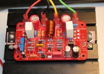 Quasi finisched.jpg148.6 KB · Views: 991
 -
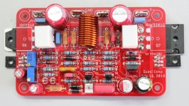 Quasi 2 finished.jpg175.6 KB · Views: 952
 -
BOM Quasi avec corrections 22 Sept 2018.pdf132.8 KB · Views: 248
-
Schema Power Supply Quasi.pdf107.3 KB · Views: 226
-
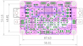
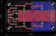 PCB Power Supply Quasi dual GND plane.png70.8 KB · Views: 972
Thanks Marc, yes I have taken the latest BOM where you have replaced the LEDs with 1N4148 diodes. Will see the schematic for the diode orientation. I have few 10000uf/50v electrolytic capacitors for the CRC psu boards and I will stick to 42 VDC as I have a medium sized cabinet with not so big heat sinks. Maybe with 50v caps i will be close to the DC voltage or should I go with 63v?
Thanks again.
Thanks again.
DC Protection
1 circuit . 30V DC trigger Triac and protect speaker if amplifier device fails
2. Circuit 8V DC trigger Triac and protect speaker if amplifier device fails
If you have rail > 30V you can take circuit 1
because SBS 2n4992 for circuit 2 not easy to get
need order by mouser , farnell ...
circuit 1 devices easy to get
Normally amps have Rails > 30V no need circuit 2
THIS CIRCUITs works in any amplifier from 1W - 5000W
Its from PA, never I have lost speaker against DC since using crowbar
Hi, I'd like to use circuit N°1 for the new ampli I am building.
Could you please give values for the power of resistors and voltage for capacirors?
Also, the triac need to be on heatsink or not?
Thanks
Michele
I have got this cabinet so the heat sinks are not so big but I feel it can accommodate compared to your small cabinet. But anyway I am not intending to run a higher powered amp but more like a simple Class A on the likes of AmpCampAmp (ACA)
HIFI audio amp Aluminum case 2412C Full Aluminum Amplifier case /Mini AMP Case/ Preamp Box/ PSU Enclosure 240*120*271mm-in Amplifier from Consumer Electronics on Aliexpress.com | Alibaba Group
HIFI audio amp Aluminum case 2412C Full Aluminum Amplifier case /Mini AMP Case/ Preamp Box/ PSU Enclosure 240*120*271mm-in Amplifier from Consumer Electronics on Aliexpress.com | Alibaba Group
Hi manniraj,
For the PSU I have used 4700 uF 63 V Nichicon LLS1J472MELA Capacitors, 0.22 ohm 5W power resistors and CBU10B bridges... I enclosed the schematic and again see comments in the tread
Regards,
Marc
Hello Marc,
I hope with your CRC psu being used as dual mono but with single transformer of dual secondary from the link (Talema - 30V 5A*2) works without any hum issues. Do you have any hum issues running 2 PSu boards with a single transformer?
Thanks
Figure out the dissipation, IsquaredR. Even at 5A, the dissipation is only 4.5W, but it's only 50% duty cycle because it's push pull, so it's a max of only 2.25W. Average with music at full power it will be around 60% of this, only 1.3W, so a 3W is just fine.
HD
Thank you.
Thank you,
Marc, the bridge rectifier "CBU10B" for the CRC psu boards, can you please give the link where you brought them. Also unable to get the right orientation of the 1N4148 diodes in place of the LEDs by looking at the schematic, may be I am missing something. If someone can provide me the anode/cathode orientation of the leds on the board it would be great.
Thanks again.
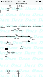
I was reading in the thread of making the 1.5uH inductor coil myself. Just wanted to know what gauge enamelled wire should I look for how many rounds as you did Marc.
I find this calculator useful for making inductors:
Single layer air coil calculator
Thanks this is very good

Thank you,
Marc, the bridge rectifier "CBU10B" for the CRC psu boards, can you please give the link where you brought them. Also unable to get the right orientation of the 1N4148 diodes in place of the LEDs by looking at the schematic, may be I am missing something. If someone can provide me the anode/cathode orientation of the leds on the board it would be great.
Thanks again.
Can anyone please let me know the bridge rectifier used here? Can I use any other as well but to know that I just wanted to know what is the exact one that is used and look for similar kind locally.
Thanks
It is not CBU but KBU10B and if you make a search on Google you find it immediately :
KBU10B DC COMPONENTS - Single-phase bridge rectifier | TME - Electronic components
KBU10005 GeneSiC Semiconductor | Mouser France
https://www.dccomponents.com/upload/product/original/281444740398.pdf
etc........
Please try to make a little by yourself before to ask others
KBU10B DC COMPONENTS - Single-phase bridge rectifier | TME - Electronic components
KBU10005 GeneSiC Semiconductor | Mouser France
https://www.dccomponents.com/upload/product/original/281444740398.pdf
etc........
Please try to make a little by yourself before to ask others
It is not CBU but KBU10B and if you make a search on Google you find it immediately :
KBU10B DC COMPONENTS - Single-phase bridge rectifier | TME - Electronic components
KBU10005 GeneSiC Semiconductor | Mouser France
https://www.dccomponents.com/upload/product/original/281444740398.pdf
etc........
Please try to make a little by yourself before to ask others
Thanks Marc, your post 2383 was listed with CBU
.Also if you guide me on how to mount the 1N4148 diodes in place of LEDs the orientation it will help in finishing the amp boards. By the way can I use 6300uf or 4700uf 50v caps for your CRC psu boards. I think the voltage may be close enough with the input but should be safe enough right?
Any thoughts on how best do I determine the required bias voltage?
thanks
You really need a Vbe multiplier and a constant current source.
- Home
- Amplifiers
- Solid State
- Very simple quasi complimentary MOSFET amplifier