Hi Prasi,
I started a schema with the UPC1237, but the test I have done on a Chinese module ( Dual channel UPC1237 Speaker Protection Board Kit Boot Delay DC Protection DIY | eBay ) were not so good 😡
Best regards,
Marc
Hi Marc .. What did not like using UPC1237?
Best regards,
Hi Jotha,
I made some test with a Chinese protection module based on the UPC1237 ( Dual channel UPC1237 Speaker Protection Board Kit Boot Delay DC Protection DIY | eBay ) and the results were not very good, I would not protect expensive speakers with them 🙁
Anyway, I have bought 10 of these integrated circuit to make a more improved PCB but I would prefer a solution with discrete part that you can chose from reliable supplier !
For the time being, I am trying to improve the third version which seem to be the preferred one by audio specialist ! I have still to calculate the value of some components...
I am surprised to see that most project here do not include speaker protection ?
I agree also with project16 that MOSFET could be a good solution and I have considered the 21st Century DC Protection board with MOSFET and MCU but it is too big for a small amplifier, may be a compact version of the one presented on post 1412 ( How to build a 21st century protection board ) could be interesting ? But even this one does not seem to be available ?
Best regards,
Marc
Attachments
Thank you Prasi for this link, I did not know this scheme.😉
Personally on my USSA-5 my protection DC with delay and detection DC adjustable which works very well, it equips some amplifiers and I have for the moment no bad return.
Attachments
In Australia we only ever use one language
The Australians' command of even that one is debatable sometimes. 😛
All joking aside, I think this is the curse of the English speaking world. I'm English and speak French, having worked there, but English people look at me as if I have 2 heads when I use it. I don't know more than 2 other English people who speak *any* foreign language fluently. Meanwhile the other week I met a German automotive engineer who speaks better English than I do, French to a fairly good standard, Mandarin Chinese, some Japanese and a few words of Korean. Of course she does, it makes it easier to work with Kia and Daewoo. Yet it's Britain, apparently, who are going to go out and trade with the world in 4 months' time!
Thank you Prasi, I may consider this design however I think the input detector is still very basic because it does not include any rectifier and the negative trigger use a transistor in common base which will not be very sensitive for low DC voltage 😕
I have also found that most protection modules use a 10 A relay, but this is a value for AC and for DC it is critical in a powerful amplifier because there is no 0 Volt crossing and the relay cannot support some possible arcing due to high current without being damaged ! I make the choice of a bigger relay with contacts specified @ 30A for 240 VAC instead of 10A 😉
This is why the MOSFET approach can be interesting...
Project16 do you have more info about your design, like schematic and features like the voltage to trigger the relay ? I could be interested to make a PCB with speaker connector on it based on your solution if you agree 🙂
Thanks for your help,
Marc
No problem, I will find the necessary in my archives.Project16 do you have more info about your design, like schematic and features like the voltage to trigger the relay ? I could be interested to make a PCB with speaker connector on it based on your solution if you agree 🙂
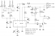
For more information the project is based on a very used and proven diagram with some adaptations for my needs.
- DC detection adjustable from +/- 0.6V to +/- 1.5V or more
- Adjustable start delay up to 5 seconds
- Supply voltage from + 12V to + 50V
- Second-order detection filter which makes it possible to avoid activating DC detection at very low frequencies that could be confused with DC.
- Use of two TLP3906 (one possible) with a current of 14mA under 9V to optimally control the mosfet gates (important for the damping factor)
Only some resistances are to be chosen according to the need.
Hi Project16,
Is your project similar to the one of J. Hofland published on post 333 here : Speaker Turn On Delay and DC Protector Board Set (V3) ?
I see that he is using op amp instead of transistors, I think he cannot use high voltage and that is the reason for 5 V regulators. I would prefer to use the amplifier power lines +/- 40 to 50 V DC for the protection circuit with 2N5551 and 2N5401 transistors...
Why you didn't use SMD MOSFET since you already use SMD TLP3906 !
Cheers,
Marc
Hello Marc
I did not use SMD components because I took over the drawing of my first version which was relay but a SMD version is quite possible and I confirm that it uses the power supply lines of the amplifier, for the TLP3906 only from the SMD and some possible in DIP version too expensive.
The diagram of the post 333 is interesting but in my humble opinion with a voltage and intensity as low on the optocoupler mosfets can not drive in an optimal way, more references chosen are not the best on their RDSON.
😉
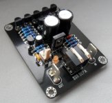
Just to throw this out there, I use a protection board I found at DiyFan.com. It's based around the uPC1237 IC. It seems to work pretty well. Attached are the schematic and hook-up files and a picture of the one I just built. I have a few extra boards if you want one. Let me know.
P.S. Moderators, I posted this in another thread by mistake. Hope that's ok. If not, the other post can be deleted.
P.S. Moderators, I posted this in another thread by mistake. Hope that's ok. If not, the other post can be deleted.
Attachments
Hi Ripcord,
Thank you for your feedback and your nice offer 🙂
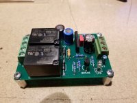
I have also tested several UPC1237 protection modules, but the results were not very consistant ! I have just bought another one because it is using bigger relay : Assembled Speaker Protection Board 30A for Audio Amplifier Amp Omron Relay Delay | eBay
Most of these DC protections use a 10 A relay which is enough for up to 50 W amplifiers, but a 30 A relay is more secure for 100 W and more amplifiers because relays are specified for AC control, however DC switching is more critical since there is no return to 0 Volt and there could be some arcing between the contacts 😡
May be the best solution is to use MOSFET like the design of 21st century protection ( How to build a 21st century protection board ) or LKA SSR Amplifier Protection, post 639 here : Output Relays and post 23 here : SSR for speaker protection?
Project16 also made a Solid State Relay protection and give me some useful informations to design my protection module 🙂
I will keep you informed of my progress...
Rgds,
Marc
Thank you for your feedback and your nice offer 🙂
I have also tested several UPC1237 protection modules, but the results were not very consistant ! I have just bought another one because it is using bigger relay : Assembled Speaker Protection Board 30A for Audio Amplifier Amp Omron Relay Delay | eBay
Most of these DC protections use a 10 A relay which is enough for up to 50 W amplifiers, but a 30 A relay is more secure for 100 W and more amplifiers because relays are specified for AC control, however DC switching is more critical since there is no return to 0 Volt and there could be some arcing between the contacts 😡
May be the best solution is to use MOSFET like the design of 21st century protection ( How to build a 21st century protection board ) or LKA SSR Amplifier Protection, post 639 here : Output Relays and post 23 here : SSR for speaker protection?
Project16 also made a Solid State Relay protection and give me some useful informations to design my protection module 🙂
I will keep you informed of my progress...
Rgds,
Marc
Most of these DC protections use a 10 A relay which is enough for up to 50 W amplifiers, but a 30 A relay is more secure for 100 W and more amplifiers because relays are specified for AC control, however DC switching is more critical since there is no return to 0 Volt and there could be some arcing between the contacts 😡
Indeed. I have several relays downstairs which are welded shut. They didn't protect anything either. All from "professionally" designed circuits.
Once you get beyond four dozen volts DC or thereabouts you need to actively quench the arcing or use solid state relays. Or use proper fuses.
In my limited experience slow blow fuses (in the power rails) best match the thermal behaviour of a voice coil without getting too close to the sound. (But, again, in my experience, they won't protect output devices or circuit boards)
Last edited:
thoglette, agree with what you say and would add that in my experience properly sized fast blow fuses in the supply lines (after the bulk caps) are the best protection without resort to fancy limiting circuits or a fuse in series with speaker, with its questionable effects on sound quality.
My fusing scheme is thus:
1. Slow blow mains AC fuse to protect the house from burning down
2. Slow blow fuse on each transformer secondary to protect the transformer from burning out if the main rectifier diodes short.
3. Fast blow fuses on the PA rails to protect the voice coils (won't save the electronics regardless what people might think!)
Some may think the above is overkill but its become second nature to me to include these on the various PCB modules and contributes negligible cost and complexity.
Hi Thimios, thoglette, Ranchu32, NMOS,
I agree with Thimios that the 21st Century Protection board is the most complete solution but it is far too complicated for a small amplifier 🙁
I fully agree also with you about relay problems with high DC current and this is the reason which convinced me to forget the relay solution. In addition, Project16 was very nice to give me enough information about his circuit to make my own protection module PCB on my specific form factor 🙂
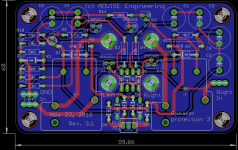
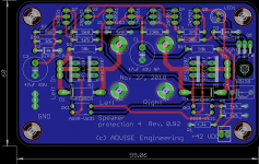
I made this PCB with the same size of the Quasi amplifier and the Quasi CRC power supply, but it is a stereo module that will be fixed on the rear panel directly on the speaker connectors (remember that I am using a very compact enclosure and I am limited to 60 mm height) !
Now, if I don't have any error, I will have to wait for the PCB before to finish completely this nice small amplifier 😀
Thanks for all your good suggestions,
Marc
I agree with Thimios that the 21st Century Protection board is the most complete solution but it is far too complicated for a small amplifier 🙁
I fully agree also with you about relay problems with high DC current and this is the reason which convinced me to forget the relay solution. In addition, Project16 was very nice to give me enough information about his circuit to make my own protection module PCB on my specific form factor 🙂
I made this PCB with the same size of the Quasi amplifier and the Quasi CRC power supply, but it is a stereo module that will be fixed on the rear panel directly on the speaker connectors (remember that I am using a very compact enclosure and I am limited to 60 mm height) !
Now, if I don't have any error, I will have to wait for the PCB before to finish completely this nice small amplifier 😀
Thanks for all your good suggestions,
Marc
Attachments
Hi Thimios, thoglette, Ranchu32, NMOS,
I agree with Thimios that the 21st Century Protection board is the most complete solution but it is far too complicated for a small amplifier 🙁
I fully agree also with you about relay problems with high DC current and this is the reason which convinced me to forget the relay solution. In addition, Project16 was very nice to give me enough information about his circuit to make my own protection module PCB on my specific form factor 🙂
I made this PCB with the same size of the Quasi amplifier and the Quasi CRC power supply, but it is a stereo module that will be fixed on the rear panel directly on the speaker connectors (remember that I am using a very compact enclosure and I am limited to 60 mm height) !
Now, if I don't have any error, I will have to wait for the PCB before to finish completely this nice small amplifier 😀
Thanks for all your good suggestions,
Marc
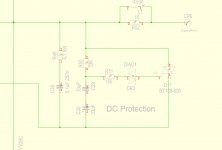
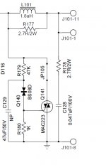
DC Protection
1 circuit . 30V DC trigger Triac and protect speaker if amplifier device fails
2. Circuit 8V DC trigger Triac and protect speaker if amplifier device fails
If you have rail > 30V you can take circuit 1
because SBS 2n4992 for circuit 2 not easy to get
need order by mouser , farnell ...
circuit 1 devices easy to get
Normally amps have Rails > 30V no need circuit 2
THIS CIRCUITs works in any amplifier from 1W - 5000W
Its from PA, never I have lost speaker against DC since using crowbar
Attachments
Last edited:
Hello Marc, if you use something like this, then there is no need for corner mounting holes
http://www.farnell.com/datasheets/1...1.1684248944.1543365344-1146205604.1543365344
https://www.mouser.in/datasheet/2/215/019-741888.pdf
It will become very convenient.
Regards
Prasi
http://www.farnell.com/datasheets/1...1.1684248944.1543365344-1146205604.1543365344
https://www.mouser.in/datasheet/2/215/019-741888.pdf
It will become very convenient.
Regards
Prasi
Last edited:
Crowbar protection circuits are suitable only for amplifiers that using fuses on rail voltages
Usually you still need relay or other circuit for noise free on an off.
Usually you still need relay or other circuit for noise free on an off.
Last edited:

- Home
- Amplifiers
- Solid State
- Very simple quasi complimentary MOSFET amplifier