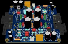
Hello everyone, I really like the layout of Marc's design board. Based on this, I modified and adjusted the position of some parts to make my own board.
The project is launched in: http://bbs.hifidiy.net/forum.php?mod=viewthread&tid=1503353&extra=page=1
The project is launched in: http://bbs.hifidiy.net/forum.php?mod=viewthread&tid=1503353&extra=page=1
Attachments

Hi again
i read all pages from page 62 started. i have just to clarify something:
I use the DACZ PCB single sided
chris
i read all pages from page 62 started. i have just to clarify something:
I use the DACZ PCB single sided
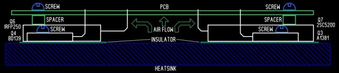
- Q4 should be mounted on the heat sink.
- Q3 mounted on the heat sink too?
- Q5 can stay up and need no small heat sink?
chris
Last edited:
i try my best to note important thinks and some links to other topics. my work should be a big thanks to the community
here are my notes from page 62 in excel...please ignore some comments from my side on the right side.
the other summary is done from another member -page 1-75
chris
here are my notes from page 62 in excel...please ignore some comments from my side on the right side.
the other summary is done from another member -page 1-75
chris
Attachments

Can someone tell me the reason to using BJT ( in negavite phase) instead of Nmos to get full quasi Nmos ? and can change 2SC5200 by IRF240/250 ?
To increase headroom at the negative clip. Neg clip is within 1.5v of pos clip giving a little more output from existing rails.
It also enhances second harmonic because the transconductance of bipolars is higher than MOSFETs.
Besides it looks cool....
HD
It also enhances second harmonic because the transconductance of bipolars is higher than MOSFETs.
Besides it looks cool....
HD
Any update here ?Installed R6 15k ohm and changed the trimmer pot to 500R. The best I could do is around 225mV for the offset. Offset was jumping around like an Aussie jack rabbit 😉. Trimmer did not really do much.
I am not happy with the flying leads and the way I have soldered up the boards with some components, so I am going to take a break, enjoy my holiday in Mexico, and then come back and rebuild ( ie: simplify ) portions of the board.
This amp is too good to walk away from, so thanks for all the help, and I will get back at the project in May 2023. Have a great new year and best wishes to all.
Adios Amigo's
@meanman1964, I have shelved the project for now and I am working on the AN39 Class A amp. I will be looking at the Quasi in the fall/winter, as I have a couple of suitable heatsinks, and I will get rid of the flying leads, and redo the layout. Thanks for asking.
MM
MM
Hi all,
Wishing a merry Xmas and happy holidays to all.
@ holts, nice pcb work. Wondering if you have built this version and listened to the result?. Also, if working OK, would you have extra pcb or gerbers available.
To all North American builders: Would anyone have a spare Dacz board? I have been changing from flying leads to normal heatsink mounting of the pcb. One channel powers up nicely while on the other channel I smoked the 2 x 0R33 5W resistors. I have not had a chance to check the bad channel yet. This board is showing signs of stress from all the re-work done, so would like to have new one. Let me know if any boards (1 or 2) available in North America 🙂
Hi to all,
Happy new year.
my VSQA is alive!!!
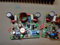
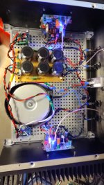
but my VSQA into my old housing of my FX8(4Ux300mm). CRC is hand made (3x 33mF each rail, with active rectifier-LT4320). i use a 300VA 24VAC transformer. i get exactly 34V per rail.
i use FQA44n133 as N ch MOSFET and the Toshiba 2SC5200 (TO264).
my test on the bench was with 32V and i use a bias setting so that i have seen 300mA quiescent current. i got after warming up and adjust the DC offset on both channels 0,6mV DC offset...that is fine. the transistors just get about 10Watt and the are really "cool"
now in the complete amp i have 34V on the rails and i have to re check the DC offset.
i use green and blue led-> yes the blue LED is really powerful... 😉
i do not expect some troubles, but i will check the fg/step response and the power At 8R and 4R after setting the bias/DC offset. the heat sinks just have a easy life.
what makes me a little nervous is the fact that i have no fuses and no SSR.
listening test will be after my tests- so in the next days.
kr
chris
Happy new year.
my VSQA is alive!!!
but my VSQA into my old housing of my FX8(4Ux300mm). CRC is hand made (3x 33mF each rail, with active rectifier-LT4320). i use a 300VA 24VAC transformer. i get exactly 34V per rail.
i use FQA44n133 as N ch MOSFET and the Toshiba 2SC5200 (TO264).
my test on the bench was with 32V and i use a bias setting so that i have seen 300mA quiescent current. i got after warming up and adjust the DC offset on both channels 0,6mV DC offset...that is fine. the transistors just get about 10Watt and the are really "cool"
now in the complete amp i have 34V on the rails and i have to re check the DC offset.
i use green and blue led-> yes the blue LED is really powerful... 😉
i do not expect some troubles, but i will check the fg/step response and the power At 8R and 4R after setting the bias/DC offset. the heat sinks just have a easy life.
what makes me a little nervous is the fact that i have no fuses and no SSR.
listening test will be after my tests- so in the next days.
kr
chris
Attachments
-
 test with 32V_300mA_iq_1.jpeg192.1 KB · Views: 141
 -
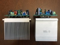
 Q4_mounting with MOSFET together_3.jpeg268.7 KB · Views: 157
 -
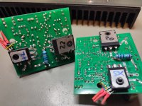 Q4_mounting with MOSFET together_2.jpeg297.2 KB · Views: 155
 -
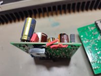 Q4_mounting with MOSFET together_1.jpeg155.6 KB · Views: 135
 -
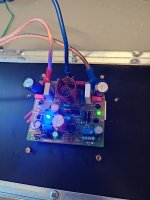
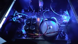 fire up with 34V_2.jpeg186.1 KB · Views: 128
 -
 fire up with 34V_1.jpeg248.1 KB · Views: 134
Happy new Year Hugh and all other members!
i take time to settle the bias at the beginning before i hear my KEF R7 , NADA DIY. all 20 minutes i set a bit the pot to finally 1mV for both channels.
i just measure shortly the signal over the amp. then i burn in over night with 4R and about 4Watt a sweep to be sure that everything is fine.
the transistors get warm (40°C) and the heat sink too but 4U 300mm can handle this cooking 😉. i checked the Dc offset and was a bit scared because i have got about 130mV and after 20-30second still 70mV. so i set the DC offset again. i guess that was nonsense because during normal listening the amp is much cooler. so i re set it again. no signal + input shorted...
listening:
source is DAC PS audio, pre is my Nuvista 600 pre (as always).
the amp has a very pleasant sound. maybe i am lucky with the mix of my transistors i do not know. after 2 days listening i must say this amp i magic👍
any kind of type of music sounds live and the control and "handling" in bass is always quick and controlled and let the sound more "rolling out" and that is for me a good sonical character! - the sound stage is not super deep and wide but it is realistic. highs feel open and clear-never hard and tend to be on the boarder of z, ts, sss and so on. texture and separation is fine - not super sharp like a scapel but not mixed voices and instruments to closed together that you have the feeling that a complex passage is just a chaos. the amp is a good mix of a generally lay back character with a small idea of forwarding sound around the mids. i have ACA with premium mods, FX8, FH9, AA14, M2, mooly amp...i know the M2OPS by my brother (DIYHarry) very well.
so you are right -this is a fantastic sounding amp your VSQA. it is a very good mix of different sounding amps.
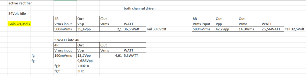
power:
during setup on my bench is set with 32V about 300mA idle- so i expect a bit more during real operation with 34V. i do not measure, transistors are in idle status very cool, heat sink too.
power you see at the pic: 25,5 WATT at 8R and about 36,6WATT at 4R i enough for home use and more.
fg high i did with 5 WATT and it is about 220khz!

step response i do not measure - but i do not expect troubles.
for more power it would be interesting to build a big Quasi....maybe...will see...
so my comment is - build that amp- it is very easy to build and cost not much --->you get a nice sounding amp.
kr
chris
i take time to settle the bias at the beginning before i hear my KEF R7 , NADA DIY. all 20 minutes i set a bit the pot to finally 1mV for both channels.
i just measure shortly the signal over the amp. then i burn in over night with 4R and about 4Watt a sweep to be sure that everything is fine.
the transistors get warm (40°C) and the heat sink too but 4U 300mm can handle this cooking 😉. i checked the Dc offset and was a bit scared because i have got about 130mV and after 20-30second still 70mV. so i set the DC offset again. i guess that was nonsense because during normal listening the amp is much cooler. so i re set it again. no signal + input shorted...
listening:
source is DAC PS audio, pre is my Nuvista 600 pre (as always).
the amp has a very pleasant sound. maybe i am lucky with the mix of my transistors i do not know. after 2 days listening i must say this amp i magic👍
any kind of type of music sounds live and the control and "handling" in bass is always quick and controlled and let the sound more "rolling out" and that is for me a good sonical character! - the sound stage is not super deep and wide but it is realistic. highs feel open and clear-never hard and tend to be on the boarder of z, ts, sss and so on. texture and separation is fine - not super sharp like a scapel but not mixed voices and instruments to closed together that you have the feeling that a complex passage is just a chaos. the amp is a good mix of a generally lay back character with a small idea of forwarding sound around the mids. i have ACA with premium mods, FX8, FH9, AA14, M2, mooly amp...i know the M2OPS by my brother (DIYHarry) very well.
so you are right -this is a fantastic sounding amp your VSQA. it is a very good mix of different sounding amps.
power:
during setup on my bench is set with 32V about 300mA idle- so i expect a bit more during real operation with 34V. i do not measure, transistors are in idle status very cool, heat sink too.
power you see at the pic: 25,5 WATT at 8R and about 36,6WATT at 4R i enough for home use and more.
fg high i did with 5 WATT and it is about 220khz!
step response i do not measure - but i do not expect troubles.
for more power it would be interesting to build a big Quasi....maybe...will see...
so my comment is - build that amp- it is very easy to build and cost not much --->you get a nice sounding amp.
kr
chris
Attachments
Last edited:
oh...i forgot.
different to the schematic - i use MPC74 0,47R resistors, R1 is 332k instead of 470k
different to the schematic - i use MPC74 0,47R resistors, R1 is 332k instead of 470k
Thank you very much, Chris, a fantastic review.
Gives everyone a realistic impression of what to get when they build this excellent amplifier.
Appreciate you built it, thanks from me and from Christian.
Cheers,
Hugh
Gives everyone a realistic impression of what to get when they build this excellent amplifier.
Appreciate you built it, thanks from me and from Christian.
Cheers,
Hugh
- Home
- Amplifiers
- Solid State
- Very simple quasi complimentary MOSFET amplifier