Nice, looking forward to your review of the sound. Love the safety precautions, I get super nervous with first power up. Recently I had a cap reversed, luckily it was low voltage. Took a while to realise what I had done wrong. Now I’m super careful with cap orientation.
I found something interesting while testing the boards tonight.
I set the bias to 100mA (33mV R20) but observed it was fluctuating some.
I realised that if I put a finger near or touched C5 (33P Mica), the bias current would increase.
Just bringing a finger near and touching will get the bias to about 140mA, but if I bring my finger close quickly and hold it there, the bias can sit at around 240mA.
Wonder if anyone has come across that kind of behaviour / if it is something normal. It won't really matter in the end because the amp will be boxed up, but I'm curious anyway.
This is HF oscillation; you can verify with the Zobel 10R at the output.
If the Zobel resistor never heats during use however the amp is quite stable.
HD
If the Zobel resistor never heats during use however the amp is quite stable.
HD
I am thinking of trying IRF140 N channel fet with bootstrap on the high side and unity gain PNP darlington config on low side and test the performance of this with approx 4.7v of bias accross them.
This is primarily to avoid an elevated B- supply to get rail to rail output.
This is primarily to avoid an elevated B- supply to get rail to rail output.
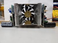
Nice tunnel cooler. Check out some large 120mm PWM fans and PWM controllers. Set to 10% and they are dead quiet. Built in temp sensor to speed up motor and also audible alarm.
Noctua NF-P12 redux-1700 PWM 9010018100365 | eBay
12V PWM PC CPU Fan Temperature Control Speed Controller Module High-Temp Alarm | eBay
Thanks X.
They look pretty good. I'm looking at using the smaller fan for this build at about 50% voltage just because the chassis I intend to use isn't much higher than the fan. I'll probably get some for another build in a bigger enclosure though.
They look pretty good. I'm looking at using the smaller fan for this build at about 50% voltage just because the chassis I intend to use isn't much higher than the fan. I'll probably get some for another build in a bigger enclosure though.
Strangely, the smoke came out of board 2 last night :-/
I put a 200mV 1KHz signal in but the output across the 8ohm dummy load looked horribly distorted. In under a minute, the PSU went into protection mode and the dreaded smell appeared soon after...
Appears the IRFP250 oscillated to death :-/ Although the signal generator is new to me so perhaps it was that..
Nothing else seems to have been harmed but I'll check through the current path to the FET to be sure.
That’s the first VSQ to die a horrible oscillating death that I know of. Maybe 47pF instead of 33pF? Did you have the 1.2uH parallel 4R7 Thiele network in between the amp and speaker?
I did but I've just realised I used 1.5uH instead of 1.2uH. Not sure if that would make a difference.
It may well have just been from careless placement of the unshielded input and output test leads from the sig gen and to the dummy load.
It may well have just been from careless placement of the unshielded input and output test leads from the sig gen and to the dummy load.
1.5uH should be even better from oscillation standpoint. There is a 47R and 220pF snubber between drain and gate trick that can sometimes help in these situations. These are used on the Alpha BB amp.
Ah nuts, bummer dude. What PSU are you using?
I've got two 36v SMPS for power at the mo.
I’m putting my order in for parts, couple of questions please.
The Zenors, are the 0.5, 1.3 or 5 watt?
33p mica? Is this a silver mica capacitor?
What are the metal connections for the PSU on the pcb called?
What size trim pots 5 x 10?
C8 OPTN what is this?
Thanks gang 🙂
Edit:
Also the 220p cap, is plain ceramic?
The Zenors, are the 0.5, 1.3 or 5 watt?
33p mica? Is this a silver mica capacitor?
What are the metal connections for the PSU on the pcb called?
What size trim pots 5 x 10?
C8 OPTN what is this?
Thanks gang 🙂
Edit:
Also the 220p cap, is plain ceramic?
Last edited:
These were the parts I used from E14:
180351-2 TERMINAL, FEMALE DISCONNECT, 6.35MM
726386-2 TAB, STRAIGHT, 6.3X0.8MM
1N4742ATR ZENER DIODE, 1W, 12V, DO-41-2
The pots were 5x10. Note the PCB value of 200 ohm for the bias (as opposed to 500R on the schematic).
33p I used was a silver mica.
Search this thread for C8 as there are a few posts regarding that one.
This was the type of trim pot I used:
VISHAY T93YA201KT20 Trimmer Potentiometer, 200 ohm, 23 Turns, Through Hole, T93YA Series, 500 mW, ± 10%
VISHAY T93YA201KT20 Trimmer Potentiometer, 200 ohm, 23 Turns, Through Hole, T93YA Series, 500 mW, ± 10%
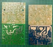
Ive got mail, yay. Feeling very grateful to Ermine22 and Avtech23 for there generosity tonight. I asked if anybody had a spare board a week ago and tonight I open the letterbox and bam! There’s two waiting for me. My plan is to build both, do a side by side comparison and then give an amplifier away as a present to a friend.
I’ve ordered two set of fets and transistors and will order the rest of the missing pieces this weekend.
Big shout out to Hugh for helping me along with this. I’ve been slowly reading through this thread and have to say that there is an amazing amount of knowledge and experience that has been shared here. I’m learning so much and haven’t even started the build.
Thanks gang 🙂
Attachments
Last edited:

I replaced the FET on board 2 today and all seems well.
I think I identified the problem... one of the test leads in the set I got had been factory assembled red-black 😱😡 I'm guessing that lead perhaps shorted the output.
Anyway, board fired up with +/-36VDC and 1KHz sine wave looks pretty good! There is some noise on the output waveform, looks like switching noise from the SMPS.
I realised I only have 4 Ohm test speakers, so apart from a brief no-input check on the noise floor, I've yet to hear if the switching noise is audible.
The output devices put out quite a lot of heat when the current is flowing! Definitely need some good heatsinking and cooling when they get boxed up!
Attachments

- Home
- Amplifiers
- Solid State
- Very simple quasi complimentary MOSFET amplifier