Trying to get it up and running. But it seems it will be a long journey!!
I can set bias OK, but output voltage is around -26V (39+39V rails).
I am using an 8 ohm resistor, and it kindly sent me some smoke signals.
VR1 is 1K. Using green led, no diodes.
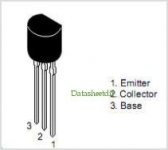
NPN is 2SD1047 (from old PC power supply, I think), and MOSFET is IRFP250 (from an ancient UPS).
Input is shorted.
Any directions?
I can set bias OK, but output voltage is around -26V (39+39V rails).
I am using an 8 ohm resistor, and it kindly sent me some smoke signals.
VR1 is 1K. Using green led, no diodes.
NPN is 2SD1047 (from old PC power supply, I think), and MOSFET is IRFP250 (from an ancient UPS).
Input is shorted.
Any directions?
Last edited:
Max,
First, disconnect the speaker. With this horrific offset it would despatch any voice coil very quickly.....
Second, with respect to black probe on GROUND, measure:
1. Voltage on gate of mosfet output device
2. Voltage on the base of the inverting transistor, and
3. Voltage at the base of the INPUT transistor.
Hugh
Max,
First, disconnect the speaker. With this horrific offset it would despatch any voice coil very quickly.....
Second, with respect to black probe on GROUND, measure:
1. Voltage on gate of mosfet output device
2. Voltage on the base of the inverting transistor, and
3. Voltage at the base of the INPUT transistor.
Hugh
Thanks, Hugh.
In fact, not a speaker, but a dummy load.
With series bulb slightly on, measured values are (no load):
+V=20,97V
-V=-17,93V
1. Voltage on gate of mosfet output device = -11,65V.
2. Voltage on the base of the inverting transistor (Q5, OK?) = around -17.8V, but not stable (slightly decaying). Q5 is MJE350G, from OnSemi, like Q3. C8 not installed.
3. Voltage at the base of the INPUT transistor (Q1=2N5401) = -16,06V.
Other guys: Q2=2N5551; Q4=BD139.
LEDs are high bright 3V models.
QAP.
Last edited:
Max,
A little weird...
What do you measure on both sides of R15? And in the junction of R12/R13?
Measure around R6, VR1 and R5 too.
A little weird...
What do you measure on both sides of R15? And in the junction of R12/R13?
Measure around R6, VR1 and R5 too.
Attachments

Last edited:
Max,
A little weird...
What do you measure on both sides of R15? And in the junction of R12/R13?
Measure around R6, VR1 and R5 too.
Attachments

Max,
Something appears (?) to be dragging Q1 to negative rail... 😕
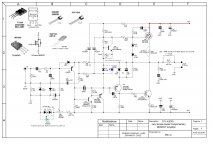
Please, measure Q2 base and collector, Q1 collector and emitter. Put values in the same schematic together with data already shown. 🙄
Maybe Hugh can perceive faster what's going on. 😎
Have you measured Q1 before mounting it?
Rgds.
Something appears (?) to be dragging Q1 to negative rail... 😕
Please, measure Q2 base and collector, Q1 collector and emitter. Put values in the same schematic together with data already shown. 🙄
Maybe Hugh can perceive faster what's going on. 😎
Have you measured Q1 before mounting it?
Rgds.
Wrong pinout
Sorry, guys, for messing with this magnificent thread. It is the first time I use a bunch of 2N5401/2N5551 I had bought from the same supplier. Unfortunately, the 5401's have different pinout from the standards. I knew it could happen, but I didn't realize it would!! Tomorrow I will replace Q1 and start it all over again. Thank you very much.
Sorry, guys, for messing with this magnificent thread. It is the first time I use a bunch of 2N5401/2N5551 I had bought from the same supplier. Unfortunately, the 5401's have different pinout from the standards. I knew it could happen, but I didn't realize it would!! Tomorrow I will replace Q1 and start it all over again. Thank you very much.
Attachments

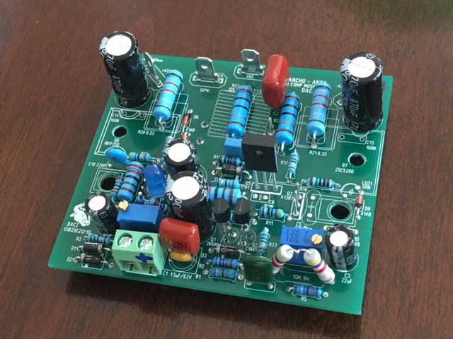
Almost done with new Dacz board. I made a few minor substitutions like 0.22R source/collector resistors and used SMT 100nF bypass caps on underside. Also 22pF NP0 SMT instead of 30pF mica. Using NJW output rather than 2SC5200. Still needs the output inductor to be rolled. It's a nice board and easily soldered with enough clearance in most places. Am I going to run into any issues with a 500R trimpot for setting offset vs spec'd 200R?
hi xrk971, can you please take the voltages so that i can update the schematic.. thanks,
dacz
Attachments
hi xrk971, can you please take the voltages so that i can update the schematic.. thanks,
dacz
Hi Dacz,
Sure, except that the amp is just in middle of getting installed in a proper case, so at present, not functioning. Maybe in a week I will have it up and running again.
Zman01 has a running amp at the moment using the exact same board. He is using a green LED rather than the two 1N4148's to get zero DC offset. I recall mine was on the verge of running out of room.
X
Last edited:
OK, it was only Q1 with inverted base and collector leads.
I replaced with another one and it started working as expected.
I set bias to 55 mV across R20, and offset voltage could be adjusted to near zero, although very unstable, but nothing to worry about.
First listening impressions are good for an amplifier built with used (and maybe stressed) power transistors, ceramic capacitor for C5, and some chinese underrated resistors (470 measured 456...).
After raising bias to around 300 mA (100 mV), it seems the overall quality got better.
Only one board has been tested, with 4 ohms load (Sony Sigma vintage loudspeakers).
I think I will try the other board with some better parts, like a genuine MJL4281AG and some other good mosfet. Hugh, do you think IRFP26N60L could do the job?
Well, that's all for now.
hi smartx21, congrats for the build. since you are now working on it kindly take measurement and update the schematic voltages. i will update the schematic once you supplied the readings.
thanks
Dacz
thanks
Dacz
Hi Max,
Yes should be OK. It should be a 26A 600V nmos and the dissipation is 450W to match the big npn.
Gate cap is just over 5nF which is fine.
DACZ thank you so much for the terrific schematic. A great schemat encourages DIYers to build a quasi!
Max congrats on finishing the quasi please let as know your further impressions as it beds in.....
Hugh
Last edited:
Some (silly?) questions for those who knows miles ahead:
1) How would I come to know if C8 is needed?
2) What could be the disadvantage of using MJE350G instead of 2SA1381 for Q5? (my case)
3) What could be the (sonic) disadvantage of using a ceramic capacitor for C5 (33p)? (my case also)
I will post some readings as soon as possible.
Thank you all for the kind words.
Hi Max,
All good questions. Here's answers:
1. C8 may be needed if the zobel 10R resistor R22 gets hot during operation. The zobel resistor on the output node, in series with C12 100nF, is a stability clamp with feedback amps and a fix for RF and EMI which can find its way into speaker lines to the amplifier. If that resistor is even slightly warm, it indicates supersonic oscillation - you can see it on an oscilloscope too. It is a sensitive test for instability at high frequency. If R22 gets hot, use C8 across base collector of the phase inverter.
2. MJE350 is a slow transistor. In scanning through pdfs from Motorola, ST, Fairchild and ON semi I have not found anything on the speed, but I seem to recall from the eighties that it's 10MHz. They are rated to 300V, 20W, 500mA and hfe 30-240 but the beta is very low, typically 75 at 10mA, and I would not use them in a VAS role. I strongly recommend the Fairchild KSA1381. They are 300V, 7W, 200mA and hfe 40-320. They are rated to 150MHz at 10mA, hugely faster than the MJE350, and very low output cap of 3.2pF. Very good transistor for a VAS.
3. There is some controversy on this cap, C5. By tradition I also use silver mica, but they are difficult to find these days. I would suggest ceramic NPO, easy to find, and they work well in the lag compensation role.
Hugh
Hello all!
Do you have a simple quasi MOSFET schematic of low power amp, something in 10W to 20W range? I don't want class A because of heat. The system is active crossover high efficiency so 10 to 20W are OK.
Thank you!
Do you have a simple quasi MOSFET schematic of low power amp, something in 10W to 20W range? I don't want class A because of heat. The system is active crossover high efficiency so 10 to 20W are OK.
Thank you!
This amp would work very well at 10W-20W range if you reduce the rail voltages to say 24V each. Some modifications would be needed to some values to accommodate lower volts. But given the low cost and the high sound quality with 42V rails, and the headroom that would offer, I cannot see any point in reducing it to 20W when the cost would be the same and it would not sound as strong. It is NOT a Class A amplifier, BTW, and the heat dissipation at idle is about 9W per channel.
Cheers,
Hugh
Cheers,
Hugh
I agree with Hugh. Unless you already have a low voltage transformer you'd like to press into service, I really don't see the point. I actually built a version of this that ran from 25V rails and it worked great with a few tweaks to a few values, but the components specified will happily run from 42V and there is no cost saving to be had by doing otherwise (unless you already have the transformer that is).
Thanks for the responses! I have a 42V rail but I read (not specific about this amp) that at very_low volume the distortion is greater than at medium-low volumes.
I have a conical horn for midbass, it is -20dB in the 70W amp I have now, -12dB in the PC EqAPO preamp, and 99% of time I listen at maximum 30% volume in Windows. That is why I am looking for a quality class AB low power amp.
I have a conical horn for midbass, it is -20dB in the 70W amp I have now, -12dB in the PC EqAPO preamp, and 99% of time I listen at maximum 30% volume in Windows. That is why I am looking for a quality class AB low power amp.
- Home
- Amplifiers
- Solid State
- Very simple quasi complimentary MOSFET amplifier