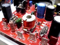
This is how my output coil looks like.
15 turns wound on a former from half an old CRT monitor transformer. 😎
(before any complaint about R25, there is another one under the board...)
15 turns wound on a former from half an old CRT monitor transformer. 😎
(before any complaint about R25, there is another one under the board...)
Attachments
Last edited:
Max,
Not critical, we need something from 1uH to 1.5uH. Too much, slows sound, too small, lets in the radio emission in the air and can cause oscillation in difficulty situations.
Nice build, some big components!
Hugh
Not critical, we need something from 1uH to 1.5uH. Too much, slows sound, too small, lets in the radio emission in the air and can cause oscillation in difficulty situations.
Nice build, some big components!
Hugh
Hi Smartx21x
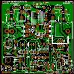
Very nice work there. Super neat. I like those tabs with little feet for perfect standup 90deg angle. Which PCB layout is this?

Very nice work there. Super neat. I like those tabs with little feet for perfect standup 90deg angle. Which PCB layout is this?
Hi, XRK,Hi Smartx21x
Very nice work there. Super neat. I like those tabs with little feet for perfect standup 90deg angle. Which PCB layout is this?
Thank you!
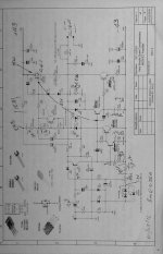
This board has been drawn by a brazilian pal (@farjon, AKA Sergio Gallo). Maybe it has been shown here before.
Hi, XRK,Hi Smartx21x
Very nice work there. Super neat. I like those tabs with little feet for perfect standup 90deg angle. Which PCB layout is this?
Thank you!
This board has been drawn by a brazilian pal (@farjon, AKA Sergio Gallo). Maybe it has been shown here before.
Hi, XRK,
Thank you!
This board has been drawn by a brazilian pal (@farjon, AKA Sergio Gallo). Maybe it has been shown here before.
See post #1347.
http://www.diyaudio.com/forums/solid-state/255427-simple-quasi-complimentary-mosfet-amplifier-135.html#post4841660
Rgds.
Attachments
Farjon,
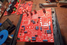
I've mounted Q4 on top of Q6 (below the board).
I had to use some wiring to reach it, though.
Is it OK?
I've mounted Q4 on top of Q6 (below the board).
I had to use some wiring to reach it, though.
Is it OK?
Farjon,
I've mounted Q4 on top of Q6 (below the board).
I had to use some wiring to reach it, though.
Is it OK?
Yes.
Another possibility is using two TO-126 dummies on top of Q6 and Q7. Then, mount Q4 direct on heatsink, below the respective position and acessing the screw by the Q4 hole on the board.
Rgds.
Attachments
G'day all,
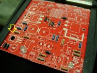
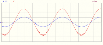
Please see attached where would this be coming from, just finished running some tests.
Used 2sa970,2cs2240,mje350, bd139, irfp240 & mjl4281 at 42v rails, bias set around 100ma but not stable when increasing signal.
Any help appreciated.
Cheers
Bruce
Please see attached where would this be coming from, just finished running some tests.
Used 2sa970,2cs2240,mje350, bd139, irfp240 & mjl4281 at 42v rails, bias set around 100ma but not stable when increasing signal.
Any help appreciated.
Cheers
Bruce
Attachments
Any help appreciated.
Now that takes me back! Final year uni project had the same symptoms. Stable at low signal levels, oscillated at high signal levels.
At the time we (my supervisor and I) believed the cause was non linearity of gain and/or capacitance which was changing the loop gain.
In my case I had mosfets "back to front" to try and mitigate the 12V Vgs "tax". The problem was that the devices I had then were extremely non-linear around device turn on. Particularly the gate to source capacitance.
I'd be looking to see if you're pushing some device into an area of operation where its gain (or Cgs/gd) are changing rapidly.
That's the "optional" C8 spot on the Dacz board? I assume NP0/C0G or better yet, silver mica is recommended here?
My own mini Quasi for headphones makes nicer sound with silver mica here.
My own mini Quasi for headphones makes nicer sound with silver mica here.
The voltage C to B or D to G can be enormous, could it be rail to rail if the amp is not oscillating, even more if there is?
Ceramics would need to be voltage specified for this duty.
Mica and plastic are easier to source for higher voltages.
Ceramics would need to be voltage specified for this duty.
Mica and plastic are easier to source for higher voltages.
Hi
No difference same with or without, how about slower device in Q7 only have mjl21194, or faster device in Q5 only have 2sb649.
Any other ideas
Cheers
No difference same with or without, how about slower device in Q7 only have mjl21194, or faster device in Q5 only have 2sb649.
Any other ideas
Cheers
Having built 3 variants of the Quasi - and they all work with great stability, all I can suggest is to switch to the recommended small signal devices. Use 2N5401 and 2N5501 and KSA1381's as a baseline case (they are plentiful and cheap). IRFP240 works I know. MJL21194 seems like it should work. Are your DC voltages at all the nodes consistent with predicted or measured points by others who have working examples?
Last edited:
Agree with X. I think maybe the input transistors should be changed, this should reduce the speed and bring back loop gain.
HD
HD
- Home
- Amplifiers
- Solid State
- Very simple quasi complimentary MOSFET amplifier