Did anyone (maybe Max in Brasil?) build the big quasi?
Any thoughts on the sound, dynamics and imaging?
Hugh
Sorry, Hugh, not yet.
I haven't even tested @farjon's board.
Too lazy for diying this year!


Sorry, Hugh, not yet.
I haven't even tested @farjon's board.
Too lazy for diying this year!
I'm selecting componentes now for the simple quasi...
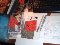
Good hear all you again. This thread had been so quiet. Any new fotos from anyone?
Attachments
Max,
No problem, we can't built amps continuously, too tiring!
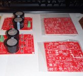
Farjon,
Very nice pcbs, good luck with it, do please let us know how it sounds!
Thiago,
Beautiful pcb, elegant and well spaced!
Hugh
No problem, we can't built amps continuously, too tiring!
Farjon,
Very nice pcbs, good luck with it, do please let us know how it sounds!
Thiago,
Beautiful pcb, elegant and well spaced!
Hugh
WHY we like a QUASI
Just to kick along this thread, I thought I'd offer WHY we like QUASIs.
First, they tend to produce high levels of H2 and H4.
Second, in the hybrid version Ranchu (Christian) and I developed, the upper nmos, driven from a bootstrap, reduces crossover.
WHY does this happen?
It is to do with the bias system and the low transconductance of the upper nmos device compared to the lower bipolar. Here is a LTSpice waveform of the output voltage (red) at 32Vpeak - over 60W from 42V rails - and the current passing (green) through the upper nmos right through the entire cycle.
If you follow the current passed with the upper nmos you will notice it never drops 18mA right through the complete waveform. (This is not that clear but if you magnify the curve is never drops below 18mA for a quiescent of 115mA). The nmos never actually turns on, in contrast to a usual conventional AB amp, where both outputs turn on and off alternatively through the cycle.
It is well understood that output device switching - commutating - causes crossover, specifically odd orders and at high levels, H5, H7, H9, H11 and even higher. There are 'machine' tones and do not sound good.
The Quasi has the upper devices constantly on, though the lower, bipolar does switch. Consequently, the odd order harmonic levels are much lower in a quasi than many Class ABs with conventional, complementary outputs. This is the reason I like the QUASI, they are audiophile friendly....
Cheers,
Hugh
Attachments
Last edited:
Member
Joined 2006
Nice amp! 🙂
Just curious....could the output BJT be easily replaced by a SiC mosfet, say SCTMU001F?
That would be very interesting if possible! 😀
SiC MOSFET MUSIC SERIES - SCTMU001F | ROHM Semiconductor - ROHM Co., Ltd.
Just curious....could the output BJT be easily replaced by a SiC mosfet, say SCTMU001F?
That would be very interesting if possible! 😀
SiC MOSFET MUSIC SERIES - SCTMU001F | ROHM Semiconductor - ROHM Co., Ltd.
Just to kick along this thread, I thought I'd offer WHY we like QUASIs.
First, they tend to produce high levels of H2 and H4.
Second, in the hybrid version Ranchu (Christian) and I developed, the upper nmos, driven from a bootstrap, reduces crossover.
WHY does this happen?
It is to do with the bias system and the low transconductance of the upper nmos device compared to the lower bipolar. Here is a LTSpice waveform of the output voltage (red) at 32Vpeak - over 60W from 42V rails - and the current passing (green) through the upper nmos right through the entire cycle.
If you follow the current passed with the upper nmos you will notice it never drops 18mA right through the complete waveform. (This is not that clear but if you magnify the curve is never drops below 18mA for a quiescent of 115mA). The nmos never actually turns on, in contrast to a usual conventional AB amp, where both outputs turn on and off alternatively through the cycle.
It is well understood that output device switching - commutating - causes crossover, specifically odd orders and at high levels, H5, H7, H9, H11 and even higher. There are 'machine' tones and do not sound good.
The Quasi has the upper devices constantly on, though the lower, bipolar does switch. Consequently, the odd order harmonic levels are much lower in a quasi than many Class ABs with conventional, complementary outputs. This is the reason I like the QUASI, they are audiophile friendly....
Cheers,
Hugh
Always very generous in sharing your knowledge
Thanks
Thiago

Nice amp! 🙂
Just curious....could the output BJT be easily replaced by a SiC mosfet, say SCTMU001F?
That would be very interesting if possible! 😀
SiC MOSFET MUSIC SERIES - SCTMU001F | ROHM Semiconductor - ROHM Co., Ltd.
My AV software blocked that link.
Maybe this one will help.
SiC-MOSFET
BTW, interesting stuff.
Member
Joined 2006
SiC diodes and mosfets are popular among diyers in Japan - for the good sound... 🙂
not yet adopted in the rest of world though....😉
not yet adopted in the rest of world though....😉
Just curious....could the output BJT be easily replaced by a SiC mosfet, say SCTMU001F?
won't this defeat the whole purpose of this hybrid BJT-MOS combo project?
Member
Joined 2006
By no means at all for any disturbance to this nice ongoing project, just sharing a thought... and a suggestion in case anyone finds it interesting to try on a new good sounding device, perhaps at a later stage ...🙂
...Inspiration actually came from AKSA's description earlier and the circuit below from Shinichi Kamijo.
...Inspiration actually came from AKSA's description earlier and the circuit below from Shinichi Kamijo.
Attachments
Last edited:
Good point, CFT. I looked over the datasheet and aside from a low 132W dissipation I feel the very low transconductance (only 2.7S at 10A, far, far less at 125mA quiescent levels) would enhance the idea of a mosfet/bipolar approach.
It should increase H2 a little more. I will examing it more carefully.........
Thank you for a helpful idea! Kamijosan is a wonderful designer, more creative than many in the west.
Hugh
It should increase H2 a little more. I will examing it more carefully.........
Thank you for a helpful idea! Kamijosan is a wonderful designer, more creative than many in the west.
Hugh
Last edited:
Driving The Quasi Transistor
This post answers a question from Max (Smart 21) about the drive on the quasi amplifier on this amplifier. I should have given the answer weeks ago, and I was wrong...... my apologies, Max!
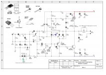
Most quasis use the same resistor value in the emitter R19 (off the output node across the Baxandall diode) and the collector R14 (across the base quasi to negative rail). The schematic is attached. I changed these equal values to R19 120R and 150R R14 on a hunch.
When we set up the bias, say around 125mA (42mV) across either of the 0.33R output resistors, we set up 6.20mA into the emitter of the inverter transistor which drives the quasi device. This means 735mV lies across R14, and if you subtract the 42mV across R21, you have 693mV across R14, which passes 125mA quiescent and 4.62mA through R14 and remaining 1.54mA into the base of the quasi device, Q7. These are LTSpice figures, in fact, but steady state and very accurate.
Since the inverter transistor, Q5, passes 6.20mA into its emitter, this current comes from the output node and via the baxandall diode D8 and the associated resistor, R19. If you pass this through a 120R resistor, the drop is 744mV, and since this current is across D8, it will be already on passing current to the inverter transistor. Spice reveals that in fact the diode D8 is on, passing 2.11mA, and the remainder, 4.09mA, is passing through R19.
There is switching taking here; the diode, the resistor, and quasi. This switching causes higher harmonics. When you measure the 120/150 combo, you get this at +20dB output, attached as Ranchu120-150.
When you measure the 150/150 combo, it's very similar here attached. I can actually see no reason to make these resistors, R19 and R14, different. They should be the same value; in this situation, I'd use 120R for both. In the FFTs, all quiescents were set to 125mA for correct comparison.
My apologies for changing horses.........
Ciao,
Hugh
This post answers a question from Max (Smart 21) about the drive on the quasi amplifier on this amplifier. I should have given the answer weeks ago, and I was wrong...... my apologies, Max!
Most quasis use the same resistor value in the emitter R19 (off the output node across the Baxandall diode) and the collector R14 (across the base quasi to negative rail). The schematic is attached. I changed these equal values to R19 120R and 150R R14 on a hunch.
When we set up the bias, say around 125mA (42mV) across either of the 0.33R output resistors, we set up 6.20mA into the emitter of the inverter transistor which drives the quasi device. This means 735mV lies across R14, and if you subtract the 42mV across R21, you have 693mV across R14, which passes 125mA quiescent and 4.62mA through R14 and remaining 1.54mA into the base of the quasi device, Q7. These are LTSpice figures, in fact, but steady state and very accurate.
Since the inverter transistor, Q5, passes 6.20mA into its emitter, this current comes from the output node and via the baxandall diode D8 and the associated resistor, R19. If you pass this through a 120R resistor, the drop is 744mV, and since this current is across D8, it will be already on passing current to the inverter transistor. Spice reveals that in fact the diode D8 is on, passing 2.11mA, and the remainder, 4.09mA, is passing through R19.
There is switching taking here; the diode, the resistor, and quasi. This switching causes higher harmonics. When you measure the 120/150 combo, you get this at +20dB output, attached as Ranchu120-150.
When you measure the 150/150 combo, it's very similar here attached. I can actually see no reason to make these resistors, R19 and R14, different. They should be the same value; in this situation, I'd use 120R for both. In the FFTs, all quiescents were set to 125mA for correct comparison.
My apologies for changing horses.........
Ciao,
Hugh
Attachments
Last edited:
This post answers a question from Max (Smart 21) about the drive on the quasi amplifier on this amplifier. I should have given the answer weeks ago, and I was wrong...... my apologies, Max!
......
Hugh
It's very nice from you remembering my name, but the doubt is not mine. I am just a simple assembler, light years away from knowing how to design and, therefore, being able to question! 😱
(some Google Translator help here...)
@CFT : Hard to get parts and looks very interesting but good for very efficient speakers only, right? 5-10W?
An LU1014D might be interesting here too for a smaller quasi headphone amp or small full range speakers. Also very low transconductance and easier to get. A pain to mount to a heatsink though. I am thinking easiest way may be to take a dead TO220 body and crack off the expoxy to expose the copper tab. Then reflow solder the LU1014D onto the TO220 tab, essentially making it a TO220 mount.
This circuit looks interesting - what does the -34v asymmetric rail provide for the input stage? Wouldn't that make it clip asymmetrically?
Is there a sim of this circuit yet somewhere?
This circuit looks interesting - what does the -34v asymmetric rail provide for the input stage? Wouldn't that make it clip asymmetrically?
Is there a sim of this circuit yet somewhere?
Last edited:
Member
Joined 2006
@CFT : Hard to get parts and looks very interesting but good for very efficient speakers only, right? 5-10W?
I suppose one can scale up the voltages a bit for achieving higher power.
Unfortunately yes, however they are still available on ebay. Replacement parts can be used as well.
BTW, there are higher power SiC Mosfets available at digikey, have a look at for instance SCT3120AL and SCT3060AL. 🙂
Last edited:
Member
Joined 2006
This circuit looks interesting - what does the -34v asymmetric rail provide for the input stage? Wouldn't that make it clip asymmetrically.
2sk70 is a V-FET; that -34v rail is for its bias purposes. 🙂
- Home
- Amplifiers
- Solid State
- Very simple quasi complimentary MOSFET amplifier