A question for the bright minded, why is a PNP input transistor chosen instead of choosing an NPN device for the input stage?
PNP transistors usually have lower noise, which is important for the input stage, while NPN transistors have higher gain, which is important for the VA stage, so it arranges nicely. Most (but not all) of the more recent upside-down designs I see around the traps use JFET inputs, which are much more commonly available in only N-CH types.
Is there a 2SK170 input stage possibility for the Quasi? Ultralow noise.
Hmm...is noise an issue with the current Quasi ? I didn't hear anyone complain. Using a 2SK170 would make it very difficult for a lot of builders due to the difficulty in getting the device.........unless it's Chinese from Alibaba ! It would also result in more complexity as you can't use it with high supply rails unless you cascode it. Then it isn't a Quasi anymore !🙂
Maybe a Coasi ?...Cascoded Quasi !😀
Nahh, noise isn't a prob on current design. I just like JFET inputs so you can have high high impedance inputs and stuff like a volume pot doesn't make scratching sounds if used without a preamp.
Andrew,
Consider the soar figures on the 4281. 100V/1A is impressive; using 56V rails and 36V (65%) and the 4R load we have 9A pk in the collector on 20V at Vce of the quasi.
I don't have the datasheet on hand but this is within its remit.
Ergo I defend my comment and contend that your 'stand and deliver' is not in the spirit of this forum. You would be somewhat circumspect in person and in this sterile environment it is very, very easy to be rude without even intending.
Merry Christmas Andrew!
HD
Last edited:
Thanks Ranchu for your input, I was actually thinking more like whether if the H2 + ...Hn signature, in general, is better with P devices.
JFET was next on my pondering list, but with a P-ch., perhaps there will be a Qrashcode in the future.. 🙂
JFET was next on my pondering list, but with a P-ch., perhaps there will be a Qrashcode in the future.. 🙂
If you only drive a resistive test load, then you can extract a lot of power from a one pair stage. And do so reliably, provided temperatures stay within your design limits.Andrew,
Consider the soar figures on the 4281. 100V/1A is impressive; using 56V rails and 36V (65%) and the 4R load we have 9A pk in the collector on 20V at Vce of the quasi.
I don't have the datasheet on hand but this is within its remit.
Ergo I defend my comment and contend that your 'stand and deliver' is not in the spirit of this forum. You would be somewhat circumspect in person and in this sterile environment it is very, very easy to be rude without even intending.
Merry Christmas Andrew!
HD
But our speakers are not resistors.
They are reactive and this reactive load places a lot more stress on the amplifier, particularly the output stages and the transistors that drive that final stage.
When one takes account of the reactive stress and the higher operating temperature, one finds that the maximum output power is a lot less than would be measured/predicted for a simple resistively loaded amplifier reproducing audio/music signals.
One must account for the effect of the reactive loading.
R.Cordell gave a guide on what is acceptable.
Jan Didden has published a guide giving similar guidance.
I adopted the David Eather analysis that Bensen turned into a spread sheet for us.
All three of these methods give similar answers. All three predict the much reduced maximum power output when reactive loads are used.
This has nothing to do with trying to be rude.
I kept quiet when you suggested some enormously high maximum output powers.
This was prompted by Xr's comment and when I saw a Member about to adopt a potentially damaging build I felt compelled to say something based on what I have learned from our other Members.
Wow, 250w from a single pair of outputs? Nice.
Last edited:
Andrew,
The problem is that all you ever do is criticise, to demonstrate how clever you are.
There are places where this is necessary, but as you appreciate, many people here are creative, and the negativity they confront with posts like yours are very discouraging. Everyone has flaws - even you - but a group can achieve remarkable things. You prefer to focus on what cannot be done, many like to as the question '...what if?'
I cannot change your approach, that is peculiar to your nature, but while you do not see yourself as rude, you see yourself as an arbiter of good sense, helping people, but you do not create at all.
There are moments on this, and other forums, where I'm pleased I sit alone at the keyboard and do not meet the protagonists.
This is an end to the matter....... BTW, reactive loads are an issue, but very few people have the bad ones, the Quads, and a few have Magneplanars which are purely resistive.
Hugh
Nahh, noise isn't a prob on current design. I just like JFET inputs so you can have high high impedance inputs and stuff like a volume pot doesn't make scratching sounds if used without a preamp.
The input impedance of the current rev. quasi is about 33k if I recall, so it wouldn't have any trouble with a 10k pot in front of it, especially if the cable lengths are kept to a minimum. The input cap (mandatory anyway with this design) eliminates DC current flowing through the wiper so you shouldn't have any problem with scratching noises.
Any modern-ish digital source should have no trouble driving a 10k pot but you might need to put a buffer in front of it if you're using an analogue source. The pot may be noisy if the source has appreciable DC offset, due to current flowing across the track ends. I've never had this problem but its something to be aware of. If that's the case then inserting one additional coupling cap, at either track end, will eliminate any possibility of DC flow through any part of the pot. A suitable cap would be in the vicinity of 47uF - quality bipolar for best results.
Hope that helps

Andrew,
The problem is that all you ever do is criticise, to demonstrate how clever you are.
There are places where this is necessary, but as you appreciate, many people here are creative, and the negativity they confront with posts like yours are very discouraging. Everyone has flaws - even you - but a group can achieve remarkable things. You prefer to focus on what cannot be done, many like to as the question '...what if?'
I cannot change your approach, that is peculiar to your nature, but while you do not see yourself as rude, you see yourself as an arbiter of good sense, helping people, but you do not create at all.
There are moments on this, and other forums, where I'm pleased I sit alone at the keyboard and do not meet the protagonists.
This is an end to the matter....... BTW, reactive loads are an issue, but very few people have the bad ones, the Quads, and a few have Magneplanars which are purely resistive.
Hugh
Add him/her to your ignore list in User CP. Maybe it will help
Hi All
Having built the amps I need to start work on the power supply. Has someone designed a single sided etchable PCB that I could build?
I have 8x 6800uf caps that can be used with a leg pitch of 10mm
Many thanks
Richard
Having built the amps I need to start work on the power supply. Has someone designed a single sided etchable PCB that I could build?
I have 8x 6800uf caps that can be used with a leg pitch of 10mm
Many thanks
Richard
try the Apex thread. Mr. Mile has many psu's, even regulated ones using 2SA/2SC TO-264 transistors. http://www.diyaudio.com/forums/solid-state/173462-studio-reference-amplifier-5.html#post2314736Hi All
Having built the amps I need to start work on the power supply. Has someone designed a single sided etchable PCB that I could build?
I have 8x 6800uf caps that can be used with a leg pitch of 10mm
Many thanks
Richard
Last edited:
Hi All
Having built the amps I need to start work on the power supply. Has someone designed a single sided etchable PCB that I could build?
I have 8x 6800uf caps that can be used with a leg pitch of 10mm
Many thanks
Richard
Easy to P2P a PSU. Or try this
http://www.diyaudio.com/forums/solid-state/297921-jumas-easy-peasy-capacitance-multiplier.html
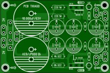
Multiplier Capacitance
Multiplier capacity based on Elliott's article.
Maybe it was useful here?
Thiago
Multiplier capacity based on Elliott's article.
Maybe it was useful here?
Thiago
Attachments
Last edited by a moderator:
if you tell me the dia of caps, i could make a simple bulk cap psu for you. like x said psu are simple to make even p-2-p. also let me know the kind of rectifier you have.Hi All
Having built the amps I need to start work on the power supply. Has someone designed a single sided etchable PCB that I could build?
I have 8x 6800uf caps that can be used with a leg pitch of 10mm
Many thanks
Richard
reg
Prasi
edit; nice job with R.E. cap mult Thiago
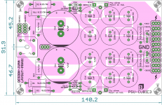
To, Tripmaster, there also a juma CM using mosfet, that i made for Cubie3. attached
Attachments
Last edited:
The ESP sch shows the second stage 470uF connected to the common zero volts point between the regulators.Multiplier capacity based on Elliott's article.
Maybe it was useful here?
Thiago
It is better to take the interference that comes through these capacitors to the zero volts line BEFORE connecting to the "clean" zero volts line.
Multiplier capacity based on Elliott's article.
Maybe it was useful here?
Thiago
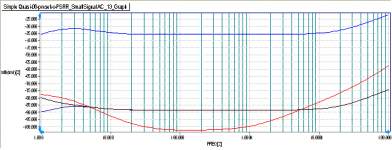
The Simple Quasi benefits with a cap multiplier on it's negative rail between the VAS and the output stage. You need only a single small signal transistor , resistor and capacitor.The PSRR on the positive rail is very good as it is. The PSRR on the negative rail on the stock circuit is relatively much poorer. With a cap multiplier it improves very significantly. Not quite sure how audible this might be. I have not built the circuit yet though I have all the parts.
On the graph, the top blue curve is the original negative rail PSRR. The next black curve is the PSRR on the negative rail with a cap multiplier and the red curve below that is the positive rail PSRR of the original circuit.
Attachments
Last edited:
Thanks All. Sorry for taking a while to respond, I have been wiped out with flu for the past week.
Thanks Prasi for the offer. I have made a few p2p PSUs in the past, but would
like another opportunity to improve my etching. I'll come back to you with some details if I may?
All the best
Richard
Thanks Prasi for the offer. I have made a few p2p PSUs in the past, but would
like another opportunity to improve my etching. I'll come back to you with some details if I may?
All the best
Richard
- Home
- Amplifiers
- Solid State
- Very simple quasi complimentary MOSFET amplifier