FQA40N25 Explanation
Hallo Hugh,
that's cool- so maouna and we all have new better option now. 😉
I am stumbled by searching datasheet FQA40N20 to the thread here:
Maya200
with your very good explained reason to use it # 10 🙂
now can start a new adventure next year.
Hallo Hugh,
that's cool- so maouna and we all have new better option now. 😉
I am stumbled by searching datasheet FQA40N20 to the thread here:
Maya200
with your very good explained reason to use it # 10 🙂
I use much bigger, 480W mosfets for the Maya, and yes, they have much higher transconductance and parasitic capacitances. The NAKSA 125 uses 280W devices.
I could fill a page on this; it's my stock in trade for the last twenty years. Firstly, higher transconductance means there is very little change in Vgs on these devices over the full waveform, and the Cgs (input capacitance Ciss) is bootstrapped by a common source configuration. These devices have transconductance around 25S plus, where bipolars are markedly less (typically 20S for a C5200), so the waveform compression of mosfets is generally superior to equivalent bipolars by 1:1. A single pair of very large mosfets are superior to multiple pairs of bipolars; more resolution and easier to drive (no gate current). It is much easier to drive large mosfets than most expect, and in fact I found using drivers increased phase shift and gave no subjective improvement in sound. We are working with audio, not radio frequencies, and up to 20KHz a high driver current is more than sufficient drive. In fact, the Maya will do huge output to 100KHz and beyond if not fitted with a mandatory LP filter.
There are some dark secrets in using mosfets in this way. They are skittish devices, inclined to self-oscillate. Robert Cordell helped me from a 1984 white paper on these fascinating devices. These days I would not use anything else, and we can thank SS traction technology for this; hybrid electronics use them in VFD modules.
Thanks Steve, absolutely, different devices, and we think, you and I, that the bigger mosfets sound as good and even a bit better.....
Hugh
now can start a new adventure next year.
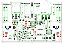
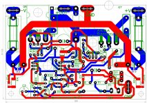
That 3rd picture, is that some kind of flower power option in your CAD program and if so what's the name of the program, nonetheless beautiful. 🙂
Hi maiko
I'm using Sprint.The tracks was formed by using curves & arcs joined and filled with "zones".It was a bit slow going at first but it picked up pace as I went along.It was also my first time using Sprint,so I played around a bit.
Regards
phunk
Thanks Phunk!
More PCB CAD companies definitely ought add a feature to convert a design into retro looks.
More PCB CAD companies definitely ought add a feature to convert a design into retro looks.
Hi Bangla H,
There are now some very good output devices in the market in both mosfet, n and p, and bipolars too. The availability of a 230W 350V $6 4281 makes it possible to make a very powerful quasi; this device is no longer the weak link on this design. Using only a single pair of outputs should mean that the crossover dysjunction is easier to control because we do not have a chorus of paralleled outputs all chiming in, all in their own key......
Most complementary designs using bipolars are up against the SOAR limitations; as you increase the collector current, the available voltage from C to E starts to shrink to avoid destroying the device. 200V 150W 15A devices become wimpy transistors with appreciable voltage across them; the C5200 can only pass 5A with 30V Vce. The problem is very serious with all output topologies, because the current rises, the voltage across the device reduces by Vcc - Vsigpk. Using a 50V rail, if the device has 20V on the load, then (50 - 20) = 30V must be across the output device. With 4R load, 20V across it (assuming very low source resistors) we have a minimal of 5A, and maybe more if its reactive. This is right on the limit of the SOAR limitations of the C5200, 30V/5A, so the MJL4281 is superior; 5A can handle 45V across the device, a huge improvement on Vce of 20V for a C5200.
In turn, this suggests we can increase the rail voltage, my suggestion for this BIG QUASI would be 56V, but of course this requires a bigger mosfet too (which BTW does not suffer from SOAR limitations to the same extent as bipolar) as suggested by the 280W FQA40N25.
HD
Last edited:
Hi All
I have started soldering and noticed that Phunk specified 5w resistors at r20 and 21. I have 2w. Is that okay?
He also has 1k8 1w at R9. I have 1k5 - is this still within spec?
Many thanks
Richard


Sent from my SM-G935F using Tapatalk
I have started soldering and noticed that Phunk specified 5w resistors at r20 and 21. I have 2w. Is that okay?
He also has 1k8 1w at R9. I have 1k5 - is this still within spec?
Many thanks
Richard
Sent from my SM-G935F using Tapatalk
Two other Candidates IRFP260N and 4229
Hi Hugh.
Thanks for explaining, sharing any more details and knowledge.
I have read a bit about SOAR- and now it's more clear- current- relation to
C-E voltage- all that little things must keep in view- and with two devices the
crosstalk between this(hfe differences) too.
My next would be order the bigger AnimalsMJL4281. Than the
Sanken 2SC3264 is out here in higher Voltage rating.
After your presenting us the very excellent FQA40N25 i was searching a bit for
alternatives and found this: IRFP260N;IRFP4229
http://cdn-reichelt.de/documents/datenblatt/A100/IRFP260N_IR.pdf
http://cdn-reichelt.de/documents/datenblatt/A100/IRFP4229_IR.pdf
possible?
FQA are in the bag- only one click.
I found also a FQA16N25- for normal Voltage use?
Hi Richard- paralleling 2x0,68 Ohm 2W or 3x1Ohm 1W possible for you?
Now it's time to go to Lounch- yummy yum.
Regards
After your presenting us the very excellent FQA40N25 i was searching a bit for alternatives and found this: IRFP260N;IRFP4229
http://cdn-reichelt.de/documents/datenblatt/A100/IRFP260N_IR.pdf
http://cdn-reichelt.de/documents/datenblatt/A100/IRFP4229_IR.pdf
possible?
There is IRFP260 and IRFP260N. 😱
What is the difference and/or suitability for audio with and without the "N" suffix? 😕
Regards.
IRFP260(N)
Nice Question Farjon.
Here two different manufacturer: Vishay and IXYS items.
Look at Rds on and all Capacities Spezial Crss- don't ask me what it all
means- that needs deeply knowledge, i don't have- always a bit stumble...😛.
http://www.vishay.com/docs/91215/91215.pdf
http://ixapps.ixys.com/Datasheet/97545.pdf
That all you can compare to FQA item than- speaks for them self.
Member
Joined 2009
Paid Member
Big FETs tend to have big capacitance and high voltage FETs in particular tend to have really high capacitance at low voltages. But if using as a Follower you are less affected by this (the Ciss is bootstrapped) so as you point out, the Crss is what you want to look at. Capacitance isn't bad in of itself providing you can drive it the issue is that the capacitance is non-linear so best to keep a decent voltage across the FET during normal listening levels. And you want to keep enough current through it so that you are getting decent transconductance. Big FETs are often shown in datasheets with transconductance measured at very high currents and can be misleading. Bipolar devices generally have much higher transconductance (good for a Follower) but it also depends on the current. From a design perspective, Bipolars have low input impedance (base current) but tend not be so tetchy in terms of parasitic oscillations - my FET designs all have zobels across gate-drain to tame that.

Thanks Gareth.
A bit about non linearity/high bias current i understand by reading Nelson Pass Articles on his pages and in threads.
I was looking to your TGM8 single rail retro threat- but it's BJT.
Wich are your design ideas with VHexFet?- missed it, must look and read to
learn. 🙂
What i read here- MosFet is permanent ON, so no charge and discharge and
low crossover distortion- is that right?
You may use 2W without any problems for r20/21 as its what the original design specified.Hi All
I have started soldering and noticed that Phunk specified 5w resistors at r20 and 21. I have 2w. Is that okay?
He also has 1k8 1w at R9. I have 1k5 - is this still within spec?
Many thanks
Richard
View attachment 582761
Sent from my SM-G935F using Tapatalk
i believe, R9= 1k5 was the original spec.
however you could use a series of resistors to give equivalent value.
Last edited:
Member
Joined 2009
Paid Member
Thanks Gareth.
A bit about non linearity/high bias current i understand by reading Nelson Pass Articles on his pages and in threads.
I was looking to your TGM8 single rail retro threat- but it's BJT.
Wich are your design ideas with VHexFet?- missed it, must look and read to
learn. 🙂
What i read here- MosFet is permanent ON, so no charge and discharge and
low crossover distortion- is that right?
If the FET is permanently 'ON' then it's Class A and Nelson is your 'man' for that.
Actually, I only used rather boring FETs so far. The full-version of TGM8 uses FETs operating in Class-C
http://www.diyaudio.com/forums/solid-state/245619-tgm8-amplifier-based-rod-elliot-p3a.html
And my earlier amplifier, TGM7, uses FETs only. The output stage of this amplifier is not my design but it works rather well indeed.
http://www.diyaudio.com/forums/solid-state/239418-tgm7-amplifier-based-greg-ball-ska.html
IRFP260(N)
Well,
Peeking around I found these two references:
# From this Thread (Hugh Dean):
"Essentially you want:
280W rating Min 150V Min 35A cont Rdson Min 120milliohms
Max 5000 pF gate Ciss TO3P through hole Single device buy"
# From Quasi Thread (Samuel Jayaraj):
http://www.diyaudio.com/forums/solid-state/43331-power-amp-under-development-221.html
"My suggestion is not to use any of the IRF devices with the suffix 'N'. If you check the datasheets you will find that the 'N' devices have lower repetitive current but higher peak current rating compared to their counterparts without any suffix; I have found that these cannot withstand the sustained current levels of output amplifiers. They are better suited for switching purposes. I am sure IRF640 without the suffix 'N' is available and should be the preferred device for this application."
Comments? 😎
Regards.
Here another one- i have build in ACA with 1,5A bias- works and in Aleph J.
http://www.mouser.de/ProductDetail/...TasSzLX0mfH0kEWRxDihHMAysMv1/LjObBAsl0fSSAQ==
there is no N- suffix.
Would you or have you build the Quasi later/now?
http://www.mouser.de/ProductDetail/...TasSzLX0mfH0kEWRxDihHMAysMv1/LjObBAsl0fSSAQ==
there is no N- suffix.
Would you or have you build the Quasi later/now?
Would you or have you build the Quasi later/now?
Smartx21 is building a VSQ with a layout of mine. See post #1616.
http://www.diyaudio.com/forums/solid-state/255427-very-simple-quasi-complimentary-mosfet-amplifier-162.html#post4882139
I'm moving right now, so my "laboratory" is packed.
In some weeks I intend to build one.
Regards.
Ho ho ho the Sinterclaas too early
Great work Marc.
Now can start the next run to build.
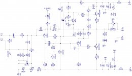
And i see in schema the IRFP4229.....hmmm.
Great work Marc.
Now can start the next run to build.
And i see in schema the IRFP4229.....hmmm.
Great work Marc.
Now can start the next run to build.
And i see in schema the IRFP4229.....hmmm.
You can use either IRFP4229/FQA40N25 and severel other devices Aksa gives in this thread....I chose the FQA40N25 instead IRP4229
Marc
[QUOTEI'm moving right now, so my "laboratory" is packed.
In some weeks I intend to build one.
][/QUOTE]
Oh sorry Farjon- any pages back and it's sunken..oh..oh.
Good luck with successful moving.
In some weeks I intend to build one.
][/QUOTE]
Oh sorry Farjon- any pages back and it's sunken..oh..oh.
Good luck with successful moving.
Smartx21 is building a VSQ with a layout of mine. See post #1616.
It is only lacking the soldering of the output network (R//L).
In fact, I'm going to build a gadget in order to help constructing a perfect coil.
- Home
- Amplifiers
- Solid State
- Very simple quasi complimentary MOSFET amplifier