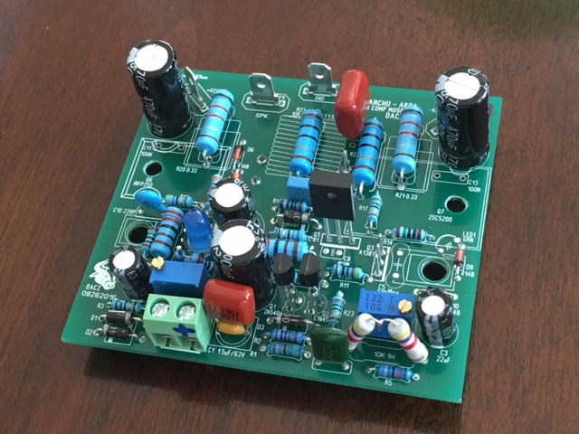
What is the used mosfet?Almost done with new Dacz board. I made a few minor substitutions like 0.22R source/collector resistors and used SMT 100nF bypass caps on underside. Also 22pF NP0 SMT instead of 30pF mica. Using NJW output rather than 2SC5200. Still needs the output inductor to be rolled. It's a nice board and easily soldered with enough clearance in most places. Am I going to run into any issues with a 500R trimpot for setting offset vs spec'd 200R?
X do you've spare boards?
Yes, but the cost to send 2 boards via USPS to Germany is only a little less than buying 10 of your own. Send me a PM if you are still interested. These are $10 for 10 from PCBway plus $11 shipping.
What is the used mosfet?
They are labeled IRFP240 and appear to have tinned legs vs satin legs. I cracked one apart (blown from thermal runaway on a different amp) and the die appears to be good. Large square centered and not covered with white RTV silicone like most fakes. Also compared to a die on a genuine Vishay and looks similar. Performance on several amps is good and sounds great.
Are they keep files for other or have to resend?Yes, but the cost to send 2 boards via USPS to Germany is only a little less than buying 10 of your own. Send me a PM if you are still interested. These are $10 for 10 from PCBway plus $11 shipping.
They keep the files but it is separate for each customer for privacy and security. It's easy to upload new Gerber on your own account.
Where are the latest gerbers?They keep the files but it is separate for each customer for privacy and security. It's easy to upload new Gerber on your own account.
What exactly is dimensions?
Last edited:
The Gerbers I used are not the latest and have problem with no holes for screws for transistors. Easy enough to drill your own holes. However, it's tested and can be assured to work. I don't know about later ones. I used the ones from post 1312:
http://www.diyaudio.com/forums/soli...mentary-mosfet-amplifier-132.html#post4837175
Perhaps Dacz can comment on whether or not there is a later Gerber with correct drill file.
http://www.diyaudio.com/forums/soli...mentary-mosfet-amplifier-132.html#post4837175
Perhaps Dacz can comment on whether or not there is a later Gerber with correct drill file.
I see post#1354 as the latest.The Gerbers I used are not the latest and have problem with no holes for screws for transistors. Easy enough to drill your own holes. However, it's tested and can be assured to work. I don't know about later ones. I used the ones from post 1312:
http://www.diyaudio.com/forums/soli...mentary-mosfet-amplifier-132.html#post4837175
Perhaps Dacz can comment on whether or not there is a later Gerber with correct drill file.
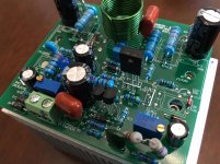
Sideview
This might be useful for those who are building this. Since the BD139 is mounted on heatsink, I left space between outputs and board for good cooling. Used a BD139 as a thickness gauge. The Allen head socket cap screws are held captive between PCB and output devices.
This might be useful for those who are building this. Since the BD139 is mounted on heatsink, I left space between outputs and board for good cooling. Used a BD139 as a thickness gauge. The Allen head socket cap screws are held captive between PCB and output devices.
Attachments
Last edited:
Hi guys
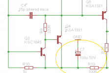
This discussion about the negative rail had me thinking, because I could have sworn that on my prototype I had a simple RC filter on the IP stage to improve the situation.
I looked back into my files for "CSH2" (my original codename for this project) and sure enough it is there... The boards I had manufactured a couple years ago were based off this schematic, and even though I've had to butcher these boards a little along the way to keep up with the changes, that RC filter on the -ve rail has been there the whole time!
So I'm not sure when that filter was dropped from the schematic and why (I can hardly keep track of this thread either!) but I'll do some listening tests over the next few days to find out whether it sounds better with or without - all this time I have been listening to it *with* that RC filter.
Attachments
Gerber Questions...
I'm interested in building this amp. The circuit is very intriguing and the development is very well collaborated. Thank you to the designers and contributors, this thread has been good reading.
Anyway, I'm contemplating sending DACZ's gerber files to pcbway for manufacturing but I'm not familiar with Gerbers and pcdway's terminology for the different board layers. Could someone please verify if my thinking is correct with the pcdway file extension naming compared to the gerber files posted by DACZ and file extension re-naming.
Pcbway file extensions........../....DACZ files
.GTL Gerber top layer............./...not used
.GTO Gerber top overlay........./...= VSQCMA_silkscreen_top.GTO
.GTS Gerber top solder.........../...not used
.GBL Gerber bottom layer......./...= VSQCMA_copper_bottom.GBL
.GBO Gerber bottom overlay../...not used
.GBS Gerber bottom solder..../...= VSQCMA_soldermask_bottom.GBS
.GKO Gerber keepout layer..../...= VSQCMA_outline.GKO
.DRD Excellon drill file.........../...= VSQCMA_drill_file.DRD
Sorry if this is stupid or a crazy looking post. I'm struggling with a tablet to write this.
Thanks, Rc
I never bothered to look at file contents other than to use online Gerber viewer to make sure it looks ok and get size to select proper price range. PCBway will have someone review your Gerbers to make sure it is good from manufacturing standpoint. That takes a day and you cannot pay until they do so. They will tell you if something is missing.
Ranchu,
I'd tried this some years back and found, on balance, that it was better to have the VAS directly referenced to the negative rail when driving complementary outputs. In this situation, with the phase inverter referenced to the quasi npn, it follows that all three stages should all be equally referenced to the negative rail. If you have a decoupler between the inverter/quasi and the VAS the hum and noise would be delivered to the inverter from the VAS output. The amplified noise on the negative rail should NOT be decoupled from the output stage and the best way around this is to delete the decoupler.
OTOH, the positive rail is already decoupled by the bootstrap; and the input singleton transistor is referenced to the input base, which is decoupled to ground. The output node, at the emitter, should be very quiet because it's a nfb node and it's source is the speaker, which is probably the quietest node on the amp.
Cheers,
Hugh
Anyway, I'm contemplating sending DACZ's gerber files to pcbway for manufacturing but I'm not familiar with Gerbers and pcdway's terminology for the different board layers.
Hi,
All you need to do is;
- Download the file "Gerber.zip" located at post 1354 of this thread.
- Send this single zipped file (do not unzip it) to PCBWay or other PCB house.
BR,
Eric
Last edited:
Hugh,
Thanks for the above comment based on your experience. It's quite an interesting anti intuitive bit of wisdom you are giving us. I have to say that I don't have any hum problems with this amp. It's very quiet. My recent experiments with Juma's Easy Peasy cap multiplier though is making me wonder if it may bring the background noise down to dead silence though.
You never got back to my question of what you meant by changing one end of R10?
Thanks,
x
Hugh,
Thanks for the above comment based on your experience. It's quite an interesting anti intuitive bit of wisdom you are giving us. I have to say that I don't have any hum problems with this amp. It's very quiet. My recent experiments with Juma's Easy Peasy cap multiplier though is making me wonder if it may bring the background noise down to dead silence though.
You never got back to my question of what you meant by changing one end of R10?
Thanks,
x
Hi X,
I take a liberty to explain what Hugh meant with regards to R10 🙂
R10 provides a bit of a local (nested) feedback from the VAS buffer to the mail feedbzck junction point.
Unsolder and lift one side of it and have a listen with no R10 in place.
Then solder it back and have a listen again.
Do you notice some difference? What option is better (with no R10 or with R10 in place)?
Cheers,
Valery
Interesting Hugh. Doug Self that demonstrated a thd improvement with the RC filter at that node, although I couldn't say whether it was with a CFP or EF2 output stage.
Have you ever tried cascoding the singleton IP and moving the comp cap connection to the cascode emitter to isolate it from rail hash? I think it was Samuel Groner who demonstrated the technique in an an audio power amp; it is commonly used in IC amplifiers apparently. Samuel's example used an LTP input but the technique is equally applicable to singleton IP of course. It can be done with one transistor, two resistors and a small filtering cap. I have used it myself in a couple of projects and didn't think it sounded worse for the cascode.
Have you ever tried cascoding the singleton IP and moving the comp cap connection to the cascode emitter to isolate it from rail hash? I think it was Samuel Groner who demonstrated the technique in an an audio power amp; it is commonly used in IC amplifiers apparently. Samuel's example used an LTP input but the technique is equally applicable to singleton IP of course. It can be done with one transistor, two resistors and a small filtering cap. I have used it myself in a couple of projects and didn't think it sounded worse for the cascode.
Valery,
Indubitably, Sir, you are absolutely right. I am still digesting your comments on EC and removal of the crossover artefacts. I am smart enough to realise I cannot disagree. Hell, you might be damn right - and if so, I learn something more about this art.
Ranchu,
Yes, I have added a cascade at the singleton and it works. I've also tried a CFP for the singleton, and the results are not so wonderful so I gave it away. My cascade is not exactly as you are suggesting, but certainly it works very well and I use it in the Maya power amp. You mention D. Self; I try to move beyond his views and opinions; he is very good at the analysis and I have learned a lot from this, but does not offer too many new topologies, which I feel are the goal of superior audio amp design. Some of the best topologies come from Valery, Alex Nikitin, Pass, Juma, Ilimzn, and JLH.
X,
Valery nailed it. Raise on end of R10 and the amp will be operating entirely in global feedback, with minimal THD. Connect up R10 and the global feedback will be reduced to 68/1.8 = 37.8 = 31.54dB. This obviously increased the THD, BUT, it does change the profile of the THD, increasing the H2-H5, and there is another effect you might find that most people would not notice at all.
BTW, to be fair, 'intuitive' logic is as often incorrect, so it's very careful to be absolutely sure of this. I explain the words nicely; the concept might not be so wonderful! A lot of dubious concepts are beautifully described with 'perceived' logic.......
Cheers,
Hugh
Last edited:
One more data point
A couple of years ago I built the basic version of Bigun's TGM8 amplifier, which is heavily based on Rod Elliott's P3A amplifier but with a singleton IP stage.
At the time I was (still am) VERY familiar with the P3A - it was one of the first amplifiers I built and I spent well over 100 hours tweaking it. I remember when I first compared TGM8 and P3A using the same basic PSU in my test rig, I felt the TGM8 was a little lacking in some respects. However then I swapped in Jason's cap multiplier that I'd built for the VSSA I also had on the workbench and TGM8 was improved, while any improvement with the P3A was negligible to my ears.
In the end I settled for a stout CRC filtered PSU on the TGM8 and like it very much, but I came away from that project thinking that some of these simple designs do require higher quality power supplies.
- Home
- Amplifiers
- Solid State
- Very simple quasi complimentary MOSFET amplifier