Hi.
This is my first post on the forum.I've "lurked" around for quite a bit.
Long story short...I've made a layout in Sprint.Thanks has to go to the previous posters who has made available their "lay" files(Thimios;Prasi;Dacz).It made the job a little bit easier.Not forgetting the huge input the OP(Ranchu32) in conjunction with Hugh Dean(AKSA) has had in component value selection.
I'm attaching the layout for perusal.Please have a look for any faults and I will correct.When the layout gurus are happy,I will upload the full Sprint "lay" file and pdf's.Don't be too harsh as this will be my first layout in quite a couple of decades and I have only been playing with Sprint for less than two weeks.
The size of the pcb is 100mmx50mm.I was looking around at pcb manufacturers online and that was the best size that would be cost effective for diy purposes.So,a bit of working backwards,and a little less surface area to work with on the pcb.
Righto..here goes.
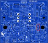
You learn fast ! Already adopted Begun's TGM1i layout, recommended by Hugh!
Check the PSRR. It's much poorer on the negative rail. If you add a cap multiplier to the -ve rail the PSRR improves dramatically. I used B2Spice.
From -35 dB to about -89 dB ( with cap multiplier) at 1Khz. Quite good all the way down to 20Hz. I'm building one and will check if this difference can make a significant difference in sound.
Hi Ashok,
PSSR on negative rail is low because voltage across bias preset Vr1 is directly related to negative rail supply. So small part of ripples in negative supply will forwarded to input of the amplifier even if a small filter capacitor c3 is present. You can improve PSSR if you connect the bias preset across the LED. Already pointed this some times back.
I'm attaching the PSRR I see using B2Spice.
The amp seems to clip first on the -ve waveform but it seems to be almost the same with or without the cap multiplier. It does clip 2 volts earlier than the +ve half. Hard clipping shows about 2 V difference.
So if we use about 36.5 V as unclipped on the negative half and 39 V as the unclipped +ve half. The possible power is 95 watts and 83 watts. That is -0.6dB loss of power due to clipping earlier. Doesn't matter much. I also checked the clipping behaviour at 20 Khz and the 1Khz square wave into 8ohm // capacitive loads. All seem to be fine.
Hi Joshvi, actually I have used the preset across the voltage reference for exactly that reason. Simulation is with that included. 10 K pot across a 3.3 V zener and 8.2K feeding the zener from the -ve rail. There is a 22uF cap from the slider to ground.
Attachments
Last edited:
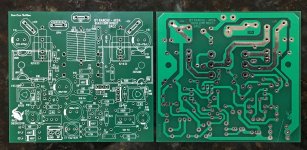
Overall nice PCB but the solder side looks a bit messy (close-up pic).
Which PCB house did you use ? Maybe Dacz could double proof and see if the Gerber file is fine.
Thanks,
Eric
Which PCB house did you use ? Maybe Dacz could double proof and see if the Gerber file is fine.
Thanks,
Eric
Why do you say it looks messy? I think you see reflections in the thru played holes that look like blobs of solder. This was PCBway - so clean boards.
Sorry, you are correct. PCBWay are indeed very good.
Hopefully Dacz can confirm if the Gerber files are OK or not for future builder.
Nice to see someone using Green soldermask, everyone is now using red.
BR,
Eric
Hopefully Dacz can confirm if the Gerber files are OK or not for future builder.
Nice to see someone using Green soldermask, everyone is now using red.
BR,
Eric
Last edited:
They arrived today from Hong Kong. Look nice except missing transistor screw holes - Gerber files should probably be corrected.
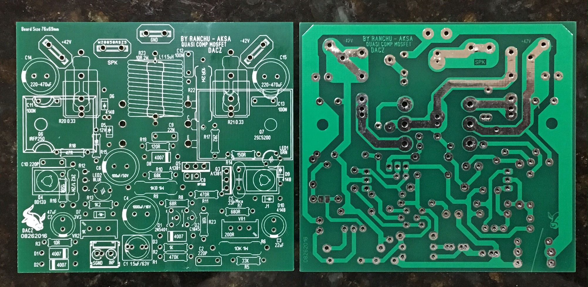
Yes, in sprint layout, when making the transistor holes, it should be made on copper layer C2/C1 (with same dia for pad and hole.). its a common mistake made in sprint, with holes defined on S1 (silk) layer.
actually sprint warns you when exporting gerbers (silk layer has holes and will be ignored or something like this).
just for info...
reg
prasi
make the holes when copper layers C2 or C1 is activated while making the sprint layout, and you will be fine.What's the solution than no holes in the silkscreen?
They arrived today from Hong Kong. Look nice except missing transistor screw holes - Gerber files should probably be corrected.
the latest gerber/pcb is here
http://www.diyaudio.com/forums/soli...mentary-mosfet-amplifier-136.html#post4842138.
the later pcb's have no hole guide.. sorry for that.
Dacz
A drill press!
Yes. Really it's not a big deal as fiberglass PCB drills like butter. I am not complaining because Dacz made a nice layout. I have a trick for the cleanest holes is to do the final diameter hole for the screw or bolt with a countersink bit - it cuts a very smooth edge on board.
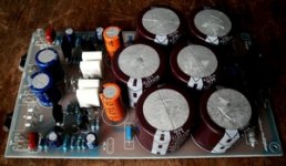
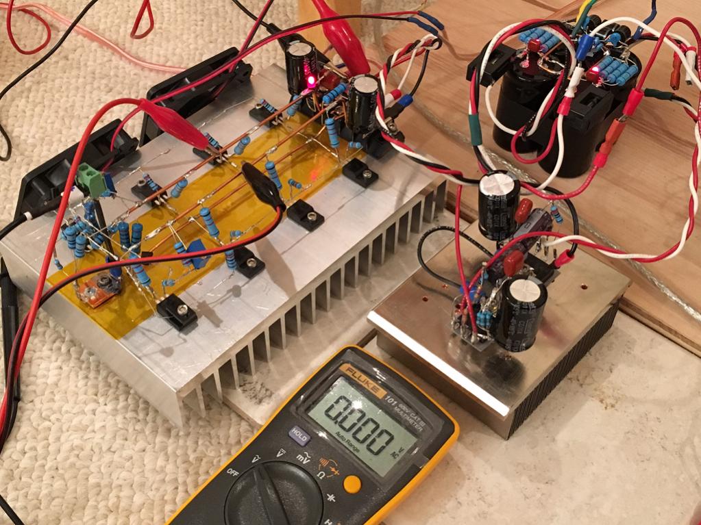
This is my PSU + Capacitance Multiplier.
For the reasons that Hugh gave, a cap multiplier is probably not needed but it did seem to help your class AB amp sound better.
For class A it's a different story as the power supply is half the amp. Having as clean a supply as possible makes a difference as bias current ripple translates directly to hum in the output on a class A.
I just built a simple cap multiplier following Juma's design for my little 2SK2013/2SJ313 F5 amp. It is so simple, just a few caps and resistors, a MOSFET and bam! it literally smashes the ripple to zero. This one uses a 4700uF cap, 220uF cap, 1uF film, 3 resistors, a 1N400X diode, and an IRFP240/9240. For a 22.5v rail, I got the ripple down from 20mV to under 1mV (shows 0mV on my Fluke DMM).
I am tempted to try it with my class AB amp just to see what happens. I made it P2P right on top of the MOSFET legs but a simple PCB might be useful as we would be using these all the time. It doesn't put out much heat that maybe including it onto future amp designs might even be possible.
Here is the schematic, I built the section after the 47,000uF cap on the heatsink. I am actually using a 33,000uF//0.125R//33,000uF CRC prior to the cap multiplier. Just make sure your caps are rated for the voltages, the multiplier will cause a voltage dropout of a few volts - so you do lose headroom. But if no PSU hum is your goal and lower level volumes is what you like, or have high sensitivity speakers like horns, this may be the ticket.

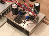
This circuit works well - I have tried other more complicated designs and they did not work as well - this one is a keeper and I will pack away in my toolbox. Here is a closeup:

Here it is in action, with the F5 drawing nearly 1.6 amps and the ripple measures 0mV with the Fluke:
Attachments
Last edited:
So we need someone to draw a pcb.🙂
Yes, maybe someone can make a small +/- rail board with under-hung MOSFETs that we can add on to almost any metal surface like a case bottom wall even, or a small CPU heatsink like I am using. Spade connectors in and out. 🙂
- Home
- Amplifiers
- Solid State
- Very simple quasi complimentary MOSFET amplifier