transformers
Hello,
For anyone here who wishes to build this amp and needs a pair of transformers, I have a pair for sale that should work nicely. These were used in a Naksa 80 for a few months but are now not being used. These will give 42v rails on US power.
Because of shipping expense, this is only feasible for US builders.
It's probably best to PM me, if interested. I can probably also adjust the price a little bit as well.
http://www.diyaudio.com/forums/swap-meet/241007-avel-lindberg-236505-a.html
Steve
Transformers no longer available
Hi Christian,
Sorry if I didn't make it clear that that the only thing I didn't like about them was that their "cheap" shipping option was a little slow. It usually take about three to four weeks to get them. I always think that won't matter but I always get anxious before they finally arrive. I'm waiting on some boards that Juan Vargas designed now. I ordered them on August 10 and they shipped on August 15th. It usually take about two weeks once they ship to get to me here in California. Not sure about Australia. Seemed like it took a long time for the package I sent to you to arrive there.
Blessings, Terry
Hi Terry
You were clear and my experience with HQ PCB has been an entirely positive to date. They despatched the boards rather quickly and at that point delivery times are out of their control. I'm generally very patient and happily chose the cheaper shipping, but I'm rather excited about this project and in hindsight I should have chosen priority shipping.
Hopefully the boards will arrive this week, at which point I will waste no time building a prototype 😀
I received my boards on the 23rd. I have already built a TO-3 BJT set and a MOSFET set. 😀 Looking to build a pair of IPS from them for the Slewmaster.
My name is Terry and I am an addict. 😀
My name is Terry and I am an addict. 😀
Terry
Your amp list is impressive. This is very good addiction, provides learning, listening to the music and lot of satisfaction.
Your amp list is impressive. This is very good addiction, provides learning, listening to the music and lot of satisfaction.
Addictions are inevitable for the human animal; it thinks, it experiences pleasure and significantly, it remembers.
Audio is a marvellous addiction for us. It is non-invasive, or criminal, or self-destructive. BUT it is expensive, it can be very loud, and it can drown out family relationships.......
You make your choices....
Hugh
Audio is a marvellous addiction for us. It is non-invasive, or criminal, or self-destructive. BUT it is expensive, it can be very loud, and it can drown out family relationships.......
You make your choices....
Hugh
Last edited:
Hugh, you definitely know what you are talking about 
There is an old skydivers' joke (which is partially a joke) on a similar matter:
"My girlfriend does not like I do skydiving. I will miss her." 😛
There is an old skydivers' joke (which is partially a joke) on a similar matter:
"My girlfriend does not like I do skydiving. I will miss her." 😛
Valery,
You have a most open, communicative temperament.......
We are all the same in this hobby, aren't we?
My wife has never tried to cure me of my addictions to powerful motorcycles, either.
Ah well, better than white powder.......
Hugh
You have a most open, communicative temperament.......
We are all the same in this hobby, aren't we?
My wife has never tried to cure me of my addictions to powerful motorcycles, either.
Ah well, better than white powder.......
Hugh

They looks nice. I hope the were worth the wait. Looking forward to hearing how they work out for you
Blessings, Terry
Blessings, Terry
Build report
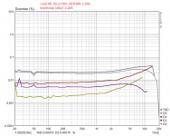
I built up a prototype today, it went off without a hitch, except that I ran out of compliance on the input bias generator: halving R13 cured that. I didn't have any 12p caps at hand so I substituted a 22p instead.
This is the first quasi I've built, the first I've owned, and one of a very few I've heard.
I want to preface all this by saying that I've only spent a few hours playing music through a single channel, in the workshop, under the house, through a bookshelf speaker. A proper listening report will follow once I get it into the living room and hook it up to a pair of floorstanders.
I've formed the opinion that capacitor burn in is a non-trivial concern. I conjecture the NFB shunt cap is particularly problematic, evidenced by my observation that circuits with a high value NFB cap (such as this) take a little while to achieve their potential.
After only an hour of listening the difference was profound and I expect further incremental improvements to come with further listening time.
This amplifier does sound better with a more bias than I'm accustomed. In this case I started with 50mA across Q6 source resistor; some crossover distortion / high frequency artefacts were evident.
With 150mA bias and a little music time on the caps it started to hit its stride: bass is prodigious for such a small amp (I can't wait to try this on my floorstanders...)
It is similar in some respects to the TGM8. Very musical once the caps had started to bed in and the bias was increased above typical levels.
I believe this has the potential to be a very good amplifier indeed 🙂
Attachments
Did you reform any of the electrolytics before assembly?I've formed the opinion that capacitor burn in is a non-trivial concern. I conjecture the NFB shunt cap is particularly problematic, evidenced by my observation that circuits with a high value NFB cap (such as this) take a little while to achieve their potential.
Ranchu
Good job !!
At least I am not alone here with your amp.. hehh.
I have spend over a week listening to this amp and must say it is really good, the most I like is top frequences - smooth and very plesent.
Please let me know how is the output offset - cold/hot differenece.
I have around 80mV drift from turn on to full heat up, but i am still working on it.
Please check that resistors before zener diode 12V are sufficient to provide enough current to the input node (i had to lower it to 2x4.7kR in parallel).
Wonderful, Christian...........
So you like it, huh?
How is the output offset and the bias stability?
Congratulations!
Hugh
So you like it, huh?
How is the output offset and the bias stability?
Congratulations!
Hugh
Did you reform any of the electrolytics before assembly?
No I did not; they went straight from the bag and onto the PCB.
Ranchu
Good job !!
At least I am not alone here with your amp.. hehh.
I have spend over a week listening to this amp and must say it is really good, the most I like is top frequences - smooth and very plesent.
Please let me know how is the output offset - cold/hot differenece.
I have around 80mV drift from turn on to full heat up, but i am still working on it.
Please check that resistors before zener diode 12V are sufficient to provide enough current to the input node (i had to lower it to 2x4.7kR in parallel).
Hi Borys & Hugh (AKSA)
I'm really enjoying the sound 😀 This morning I snuck downstairs while the family were asleep and had another listening. I dialed back the bias a little and the sound was still wonderful, leading me to think that the caps just need a little time to form properly.
DC offset
Once adjusted to 0mVdc, the offset drift is small. When I had my DMM probes connected it ranged no more than about 30mV, which I consider to be quite acceptable and comfortably under the 100mV maximum that many recommend. The drift is very slow from hot to cold and during very dynamic musical pieces.
Please note that on my layout the bias generator is back-to-back and glued to the input transistor, which might improve the situation. That said, I never found thermal drift to be an issue with the TGM8 (Bigun came up with the design) and on his boards the transistors are not thermally coupled.
There is some turn-on noise. It is nearly inaudible but there is sufficient offset to move the bass cone. No turn-off noise evident.
Output biasing
I expected bias stability to be a major issue (actually I half expected the MOSFET to go up in a cloud of smoke within minutes!). That hasn't proven to be the case at all.
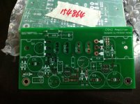
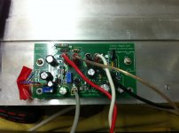
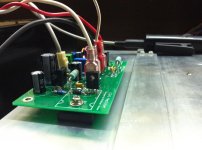
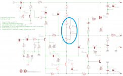
Borys, be aware that I went straight to Hugh's suggested bias generator shown in the schematic attached, instead of the simple bias string arrangement I originally designed the boards for. In the photos you can see a TO-126 sandwiched between the MOSFET and the board underside so that it tracks the MOSFET temperature. The diode is in free air per Hugh's recommendation.
With bias set so there is 50mVdc across the MOSFET source resistor, it varies between about 40-60mVdc between stone cold and hot. I don't know if this is good or not (I've seen better tracking in all BJT designs) however it never drops to the point where crossover distortion is evident, nor would it appear that thermal runaway is a concern.
Attachments
- Home
- Amplifiers
- Solid State
- Very simple quasi complimentary MOSFET amplifier