Ok,thanks for reply.🙂Unfortunately not thimios. I did a layout based on the original schematic, and have subsequently "hacked" them to incorporate several changes.
It is probable that I will revisit this at some point in the future, but it isn't a high priority at the moment. I'll update this thread with any further developments.
Going back some 10 pages or so, I think there was a missed opportunity to keep things simple (or even simpler 😛 ).
There is a bit of a mix-up with the output stage. I't a classic quasi, however the bottom is a Sziklai pair (or CFP) and in that case it's the first transistor that dictates it's nature - in other words, even though it is a combination of a BJT and MOSFET, it actually behaves like a BJT. Because of this the 0.22 ohm resistor should not be in the source of the bottom MOSFET, but rather between the connection of the drain and driver emitter, and the output.
Now, becasue of the unusual nature of a BJT CFP/MOSFET combination, there is actually more that can be done to simplify the design. For one, the R-C-D parallel combo is not necessary. This would be used if the top was a BJT darlington, and it's used to make the crossover region more symmetrical, because for the CFP it's much narrower than that of the darlington. In the case of this amplifier, it's very difficult to do this since the devices are so different. However, it is possible to narrow the Vgs range the top MOSFET works in, by excluding the source ressitor. At the same time, the 'emitter' resistor of the CFP mentioned above should be increased, perhaps to 0.47ohms.
Further, BJTs have a higher positive temperature coefficient than MOSFETs so the CFP dominates temperature stability. The nice thing about that is that the element that needs it's temperature compensated is the driver BJT for the bottom MOSFET. Because of this, a simple Vbe multiplier with the BJT thermally coupled to the driver BJT for the bottom MOSFET will do the trick, and the entire thing remains on board - no need to sense the temperature of the heatsink with the MOSFETs.
Finally, some way of protecting the MOSFET gates from overvoltage needs to be implemented.
Attachments
Last edited:
Ranchu32
That is very promising upgrade, I am just wondering if there will be no offset issues.
The very simple amps have something magnetic in the sound.
I have tryed CFP input pair and it worked very well. (still have some measurements at work).
I have spend a lot of time on that amp and found that it is very sensitive animal. Some small changes can degradate sound badly and some are giving big improvements.
Please keep us updated !!
BTW
I am going to develop Your's first version, I will try to implement DC servo instead transistor compensating DC offset.
Good point, Ilimzn, on the RCD network on the phase inverting transistor, Q4.
However, along with R15 on the source of Q5, there is some influence on the quiescent current, along with the R16 on Q6, just as you mention.
Temperature control over quiescent is tricky; it is advisable to have the bias generator in touch with the heatsink. In this case I'd probably replace with diodes with a BD139 in Vbe multiplier.
The interesting feature of this hybrid quasi is the radical difference in transconductance between mosfet and bipolar. This generates an asymmetrical waveform distortion which is mostly H2 with a bit of H3, and this confers the warm quality of the presentation.
Hugh
Last edited:
Hugh, this will depend actually on the G-S resistor of the bottom MOSFET.Temperature control over quiescent is tricky; it is advisable to have the bias generator in touch with the heatsink. In this case I'd probably replace with diodes with a BD139 in Vbe multiplier.
This is somewhat from experience as I have built a similar simple amp with BJT outputs. The CFP's front end is the determining factor, in fact it even somewhat overcompensates with a BJT, it would do that even more with a MOSFET. However, there is a remedy, and this is what I mentioned re including an 'emitter' resistor for the CFP only. This would have to be 'fairly' large compared to 0.1-0.22 ohms commonly found in BJT amps - perhaps 0.33, 0.39 or 0.47ohms. And yes, I was thinking precisely a Vbe multiplier, but in good thermal contact with the CFP front end BJT.
Yes, this is indeed the case, however somewhat remedied by the inclusion of Re only for the CFP end. There is also the question of asymmetric clipping, a diode should be added in the bootstrap chain to the positive power rail...The interesting feature of this hybrid quasi is the radical difference in transconductance between mosfet and bipolar. This generates an asymmetrical waveform distortion which is mostly H2 with a bit of H3, and this confers the warm quality of the presentation.
Hugh
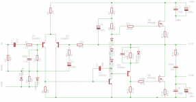
Something like this - not by far optimized, transistor types are representative (i.e BC640=BD139 in a different package), needs some refinement like gate protection, capacitor across Vbe multiplier, etc. - more of a doodle to show the idea:
Attachments
Last edited:
Interesting solution, Ilimzn, however, the great advantage of a bootstrap is that the gate can be driven above the rail, improving rail efficiency. This is very useful and improves the output to clip on positive half cycle. How about using a 4.7V zener + diode, like a gate protection approach, rather than a simple diode? It would deliver another two volts at the output.......
I like the 0.33R on the output of the CFP. Neatly gets around all the problems........ thank you!
Hugh
I like the 0.33R on the output of the CFP. Neatly gets around all the problems........ thank you!
Hugh
Last edited:
Interesting solution, Ilimzn, however, the great advantage of a bootstrap is that the gate can be driven above the rail, improving rail efficiency. This is very useful and improves the output to clip on positive half cycle. How about using a 4.7V zener + diode, like a gate protection approach, rather than a simple diode? It would deliver another two volts at the output.......
I like the 0.33R on the output of the CFP. Neatly gets around all the problems........ thank you!
Hugh
Hugh, the diode is there exactly to prevent the MOSFET from being driven all the way on the positive half cycle - in fact it woulf be beneficial if it could be clipped to an even lower value. How so? Well - as it is the amp can be driven all the way to the positive rail (without diode) but not nearly to the negative - the reason being that the drive from the bottom MOSFET comes from the difference of voltage between the negative rail and the output - that's all the CFP BJT has to work with. This is further reduced by the voltage drop on the 0.33ohm resistor, which is necessary for thermal stability. As a result, the amp clips asymmetrically as it is, by about 2-3V or so, without the diode i would be a few V more. Also, it would be in danger of developing overhang on the positive side as the gate being driven above the drain is the worst combination regarding the rise in the nonlinear capacitance of the MOSFET gate. Remember that in a way the bottom MOSFET is driven by a 'buffer' and with very low gate impedance (essentially the 220 ohm resistor) but the buffer sees the full Miller capacitance of the MOSFET. The top one, however is driven by a high iompedance (in fact, you could probably delete the gate stopper if the layout was carefully done) and looks like a follower. It would be possible to add a BJT follower to the top MOSFET for better results but then the thermal stability is a different problem...
If the clipping is clean, well behaved and recovery from clipping looks good why worry if it is a little asymmetric? You are trying to throw out one of the benefits of bootstrapping...
Here's an even simpler idea. Again, mostly developed, if you see odd resistor values, it usually means it's a trimmer (offset and bias). For the more adventurous, the 2.7k resistor between G-S of the first IRF610 (the second one is a Vgs multiplier among other things) can be replaced by a current source made out of a JFET and resistor from G to the -40V rail (adjust current for the same value as in the schematic shown). This amp effectively concentrates most of the gain to the input stage and the output stage, the middle is bootstrapped phase splitter. It is again limited from operating rail to rail on the top for symmetric clipping.
Attachments

If the clipping is clean, well behaved and recovery from clipping looks good why worry if it is a little asymmetric? You are trying to throw out one of the benefits of bootstrapping...
It would be about 5V asymmetric based on a total of 26V peak output, that's not a little. Why worry? Because it creates net DC on the output and will trip a DC protection circuit - with good reason, if the amp is driven into hard clipping there will be quite a bit of DC. With the diode it's reduced to about 2V difference, which is acceptable, AND it's cleaner (no overhang). Besides i would consider asymmetric clipping to be NOT clean.
Simulate the circuit and see for yourself - you can always remove the diode if you don't care about DC.
Last edited:

You are right, Ilimzn, I have simulated and you are correct.
Thank you for this gem, appreciated........
Hugh
Thank you for this gem, appreciated........
Hugh
I would be surprised to see this amp driven to a clipping level! If somebody would be tempted to do so, that person would probably need mental health check. DC protection circuit is only necessary for people that do not have good contact with reality. As soon as you notice any loss of clarity in sound reproduction you know that you need to adjust level to safe limits. Listeners ears are enough protection. There is no substitute for sanity. This is not monster power amp. User must be careful not to use it anywhere near clipping level. Therefore, clipping behavior should not be our concern.
Clipping levels are only allowed with tube (valve) amplifiers.
Clipping levels are only allowed with tube (valve) amplifiers.
I would be surprised to see this amp driven to a clipping level! If somebody would be tempted to do so, that person would probably need mental health check. DC protection circuit is only necessary for people that do not have good contact with reality. As soon as you notice any loss of clarity in sound reproduction you know that you need to adjust level to safe limits. Listeners ears are enough protection. There is no substitute for sanity. This is not monster power amp. User must be careful not to use it anywhere near clipping level. Therefore, clipping behavior should not be our concern.
Clipping levels are only allowed with tube (valve) amplifiers.
While I agree with your assertion that one must not ignore their ears, there are people who could not detect clipping using their ears if their life depended on it, until it goes way too far, i.e. into 'hard clipping'. Hence the 10% THD rating for output power.
As for clipping levels in tube amplifiers - I would beg to differ. Why would clipping levels be alowed for a 30W tube amp but not for a 30W transistor amp? In fact, the only difference in being able to use an amp close to clipping levels is how well behaved it is at clipping, and mostly (but it's not a rule!) tube amps are more well behaved - to a level usually, then it gets worse than for transistor amps.
Also, regarding clipping - smaller power amps are far more likely to clip. Here is an exercise for anyone with an oscilloscope - connect it to the output of the amp and just watch, even at moderately high (far from insane) listening levels - you will notice that clipping is not that rare! Fortunately it is short - but for the most part you have to get into quite serious clipping to discern it as a serious degradation, because as long as it's short the ear does a good job of masking it. This is why only a few W can sound surprisingly loud IF the amp behaves well when clipping.
You might remember that there is a rule of thumb that says you are more likely to fry your speakers with a low power clipping amp than with a power amp that can produce a clean signal well over the power handling of the speaker - although, like most rules of thumb, this is an over-generalization, it is indeed largely true. In the case of this particular amp, the asymmetric clipping will not so much generate a lot of high order harmonics, as it can generate a DC offset so, unusually, it's not your tweeters that are in danger and where you will hear problems. The woofer however will move out of center which produces other problems.
I'm not going to delve deeply into this because it's not what the thread is about. I have done extensive experiments with clipping (both tube and transistor amps) and believe me, it makes a LOT of difference how an amp clips, to the perceived dynamics of the sound it reproduces at higher volume. There are several non-obvious issues with clipping, which are not easy to solve - like modulating the clipping level with the power supply ripple.
I had a chance to test second hand UK made tube Audio Inovations 200 power amp couple years ago and I must say that this 15W per channel amp (only one pair of EL34 in push-pull) sounded better at high listening levels than any 100W solid state amp I have ever heard. I use high efficiency speakers in a small room and my impressions are probably influenced by this fact to some extent. Generally, solid state amps start to sound harsh at relatively low levels compared to their declared power. With tube amps one has the impression that the amp is much more powerful than in fact it is. That's probably due to a clipping behavior. My position is that clipping should be avoided at all costs with solid state amps, no matter if it is symmetrical or not. When it comes to subjective perception of sound, there is not quick enough recovery from clipping for solid state amps, at least to my ears.
I had a chance to test second hand UK made tube Audio Inovations 200 power amp couple years ago and I must say that this 15W per channel amp (only one pair of EL34 in push-pull) sounded better at high listening levels than any 100W solid state amp I have ever heard. I use high efficiency speakers in a small room and my impressions are probably influenced by this fact to some extent. Generally, solid state amps start to sound harsh at relatively low levels compared to their declared power. With tube amps one has the impression that the amp is much more powerful than in fact it is. That's probably due to a clipping behavior. My position is that clipping should be avoided at all costs with solid state amps, no matter if it is symmetrical or not. When it comes to subjective perception of sound, there is not quick enough recovery from clipping for solid state amps, at least to my ears.
Not all solid state amp clip badly. This amp at least on simulation, have soft clipping. But not tested yet. Few people already made PCB, may be about 3 days later we can see the result...
Clip performance on a mosfet amp
Let me offer my support to Ilimzn and his very good ideas.
I examined the LTSpice of Ranchu's mosfet/bipolar quasi, as amended with a CFP in place of the Baxandall diode concept. I set a gain of 29, input 20KHz signal, at 1.5Vp. This takes the output into hard clip, where this phenomenon is clearly seen.
The first is the macro graph without a clipping diode between gate and upper rail. Notice that the oscillation is severe on the down side of the waveform, from +40V down to +28V. This would be highly audible as a 'machine' tone, very nasty HF artefacts.
The second is the fine detail of this seen situation.
The last graph shows the macro waveform at full clip with a 4.7V zener and 1N4148 diode in series, which slices any excess potential when the gate rises (4.7 + 0.6) volts over the rails. The phenomenon is almost negligible with all HF artefacts largely removed. The two schemats and models are identical, as are the stimulus, only the additional zener and 4148 between gate and positive rail. I have examined a choice of zeners; anything from around 2.7V above - 4.7V is the same outcome - but using a zener seems to give an additional 1V of upper output over a single diode. Additional output to clip is highly useful for rail efficiency, since another 1V of output into 8R from 37.5Vp to 38.5Vp corresponds from 87.9 watts to 92.6 watts.
This is a very useful technique, and I thank you Ilimzn for his astute observations and his willingness to inform the forum.
Ciao,
Hugh
Attachments


Last edited:
Let me offer my support to Ilimzn and his very good ideas.
I examined the LTSpice of Ranchu's mosfet/bipolar quasi, as amended with a CFP in place of the Baxandall diode concept. I set a gain of 29, input 20KHz signal, at 1.5Vp. This takes the output into hard clip, where this phenomenon is clearly seen.
Hugh, careful with the sim - you might want to look at the gate drive waveform of the top MOSFET, this must never generate a Vgs > 20V for it. The simulator does not check for it, and some models misbehave. Also, models as a rule do not model the rather high increase in Cgs and Cdg at low Vds, however most MOSFET datasheets have diagrams for this. I am mentioning this because the sim might not show any difference bewteen behavior of the amp with a clipping diode anywhere form a PN voltage drop to PN+4V7 Zener at the regular 1kHz input frequency. I tend to look at 10kHz because that magnifies problems and thus reveals them.
Even so, what you did is exactly along the lines of what I was saying.
Regarding clipping asymmetry, this comes from the way the MOSFETs are driven. The bottom one can at best have Vgs=Vds, when there is no load and the BJT is saturated. In reality there will be current passing through the 0R33 resistor and therefore a voltage drop, so the clipping will occur roughly at the Vgs=Vds condition for that current, plus 0R33 times that current. On the other hand, the top MOSFET can be driven over the positive rail because of the bootstrap (unless limited by a diode or diode+zener clamp) to the point where it's Vds is very low. This is actually useful in some cases when the amplifier output is capacitor coupled, to get more power. However, in case of DC coupling, it's not worth adding power by just adding voltage to the positive half of the waveform 🙂
- Home
- Amplifiers
- Solid State
- Very simple quasi complimentary MOSFET amplifier