Yes, I am using Hugh's values for resistors and the two 1n4148's. Also, switching to 2N5551 and 2N5401 seems to have fixed the offset issue with my DC offset as I can get to and even go past zero to positive offset with 500R trimpot.
I had no luck with original ones so would go with Aksa's recommendations including swapping 2 red LEDs for 1N4148's. But I am curious why originals worked for Still4given and Thimios. Maybe you should stick with original and see if it works.
XRK,
This is wonderful news and shows that purpose, logic and some solder slinging you can do anything......
Congratulations, this has been a long haul, but significantly you found that most of the issue were too much heat on your iron!
Terry, I would very much doubt that my changes would make any difference to the sound quality. I have changed the Q1 collector resistor from 680R to 1K, and the feedback resistor from 1k5 to 1k. Then a couple of diodes in place of the redleds, and it's done. The operating points of the first transistor is moved down from 1mA to 0.65mA; not a lot, and I doubt it would change anything. The remaining transistors and mosfet are unchanged.
It might make the offset a little more stable; this is mere bagatelle.
Accordingly, I would not change the Ranchu, original values.
Cheers,
Hugh
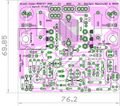
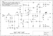
I've this boards and this is the scheme that comes with it but can I use the latest scheme 4.3?
Terry,can you help me out here?
Terry,can you help me out here?
Attachments
Last edited:
XRK,
This is wonderful news and shows that purpose, logic and some solder slinging you can do anything......
Congratulations, this has been a long haul, but significantly you found that most of the issue were too much heat on your iron!
Terry, I would very much doubt that my changes would make any difference to the sound quality. I have changed the Q1 collector resistor from 680R to 1K, and the feedback resistor from 1k5 to 1k. Then a couple of diodes in place of the redleds, and it's done. The operating points of the first transistor is moved down from 1mA to 0.65mA; not a lot, and I doubt it would change anything. The remaining transistors and mosfet are unchanged.
It might make the offset a little more stable; this is mere bagatelle.
Accordingly, I would not change the Ranchu, original values.
Cheers,
Hugh
Hugh,
Thank you for all the guidance and encouragement, and also thanks to Terry, Ranchu, Thimios, Prasi, and others that I may have missed for all your help and tips and tricks. In the end reason and dilligence won, and I gain some valuable experience that a methodical step by step dissesction of the board is the only way to solve these apparent "cursed" board problems.
I have a similar situation with a brand new Circlophone that I can't get working. I had to reinstall a few diodes and noticed flakey pads and traces. That PCB is even more fragile than this one. It has tiny tiny little circle pads on transistor legs. And there are 18 transistors I think.
Have you played it hard for an hour and then checked the offset?
Yes, it was within 6mV after 2hrs playing fairly good volume. Heatsink was much hotter.
Prasi Excel Part List
Hi meanman.
That is the list what i will use to put parts on board.
The Value of R4/5/9 and C8- should you place extra <Steckpins<?- to can
change with more comfort- i don't know exactly.
But Ranchu/Thimios and Terry have run his Amps.
Hope you could open the added list and be successful.
Cheers.
Hi meanman.
That is the list what i will use to put parts on board.
The Value of R4/5/9 and C8- should you place extra <Steckpins<?- to can
change with more comfort- i don't know exactly.
But Ranchu/Thimios and Terry have run his Amps.
Hope you could open the added list and be successful.
Cheers.
Excel not sendet
Why not?
To dumb to send back a Excel with Partlist.
Sorry.
R1-470k VR1-500R Q1- A992-2N5401
R2-1k VR2-1k Q2-C1845-2N5551
R3-10R Q3/5-A1381
R4-47k C1-1,5µ/63V Filmfoil- QXP 3- on heat sink
R5-100k(also:51k-Terry;68k) C2-220p NPO ceram Q4-BD139
R6-10k 1W C3-47µ/50v Q6-IRFP240/FQA....
R7-680R(also 1k) C4-2200µ/16/10v- low esr Q7-C5200/C3263
R8-47R C5-33p mica
R9-1,5k 1W(also 1k) C6-220-470µ/50/63v LED-2xRED max 1,6v
R10-68k C7-47µ/50v
R11-470R C8-not used- 68p NPO
R12-2,2k min. 0,6W C9-22n styro;FKP-2
R131,2k C10-220p NPO
R14-150R C11-220-470µ/50/63v
R15-1,2k C12-100n/100/63v MKT
R16-150R C11/13- 100n/63v foil RM5
R17-2,2R C14/15-220-470µ/50/63v
R18-47R C16-option play FB33-68p mica
R19-120R D1,2,3-1N4001-4
R20,21-0,33R(best) 2-3W D4-1N4002-1
R22-10R 1W D7-3,3v zener or blue LED
R23-10R D5-12V zener -1N47...
D6- 1N4148
Take a second old TO126 to space the C5200 like IRFP one- same distance.
Nothing significance forget?
 Bangla.
Why not?
To dumb to send back a Excel with Partlist.
Sorry.
R1-470k VR1-500R Q1- A992-2N5401
R2-1k VR2-1k Q2-C1845-2N5551
R3-10R Q3/5-A1381
R4-47k C1-1,5µ/63V Filmfoil- QXP 3- on heat sink
R5-100k(also:51k-Terry;68k) C2-220p NPO ceram Q4-BD139
R6-10k 1W C3-47µ/50v Q6-IRFP240/FQA....
R7-680R(also 1k) C4-2200µ/16/10v- low esr Q7-C5200/C3263
R8-47R C5-33p mica
R9-1,5k 1W(also 1k) C6-220-470µ/50/63v LED-2xRED max 1,6v
R10-68k C7-47µ/50v
R11-470R C8-not used- 68p NPO
R12-2,2k min. 0,6W C9-22n styro;FKP-2
R131,2k C10-220p NPO
R14-150R C11-220-470µ/50/63v
R15-1,2k C12-100n/100/63v MKT
R16-150R C11/13- 100n/63v foil RM5
R17-2,2R C14/15-220-470µ/50/63v
R18-47R C16-option play FB33-68p mica
R19-120R D1,2,3-1N4001-4
R20,21-0,33R(best) 2-3W D4-1N4002-1
R22-10R 1W D7-3,3v zener or blue LED
R23-10R D5-12V zener -1N47...
D6- 1N4148
Take a second old TO126 to space the C5200 like IRFP one- same distance.
Nothing significance forget?
Bangla.Note that Q3 and Q5 can be MJE350 pin compatible
Q1 with 2n5401 and Q2 with 2n5551 can work but need to swap pins 2 and 3 and cover one leg with shrink tube insulator.
Do not install R4 - my DC offset would not trim with it in place.
R5 I used 33k per Aksa
R7 I used 1k per Aksa
R9 I used 1k (must be at least 1 watt - it cooks) per Aksa
Red LEDs I exchanged with 1N4148's per Aksa
If using blue LED instead if 3.2v Zener - orient cathode opposite of Zener cathode.
My advice from hard lesson learned - try to install the correct value from the beginning. This board is very fragile and any rework will damage the pads even if you are careful. The pads simply cannot handle being heated more than once.
Last edited:
You can add it to FB Resistor- linearity- better low end- i've not notized why, only you can
place there one.
I have send you the Excel to your PM directly.
Hope is all in there now.
Cheers.
place there one.
I have send you the Excel to your PM directly.
Hope is all in there now.
Cheers.
You ar working on it or is it working?
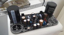
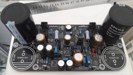
Still working .... It still lacks some parts ...
Regards
R5,VR1
Hi X.
Builders has placed R4 to 47k, R5 to 100k, and VR1 to 500R.
Is my thought right:
If i higher the value of R4- for Example 56k then drops more voltage across it
and resulting voltage to base of Q1 would reduced and lowered and same way
R5- or i am total wrong in: how works that in regulation?
I know i have to learn much more.
Bangla.
Hi X.
Builders has placed R4 to 47k, R5 to 100k, and VR1 to 500R.
Is my thought right:
If i higher the value of R4- for Example 56k then drops more voltage across it
and resulting voltage to base of Q1 would reduced and lowered and same way
R5- or i am total wrong in: how works that in regulation?
I know i have to learn much more.
Bangla.- Home
- Amplifiers
- Solid State
- Very simple quasi complimentary MOSFET amplifier