its at zero hz, so tweeters are out of question. (tweeters should not be used w/o a cap). For full rangers, even if we take a 5w sensitive speaker (fostex FF85WK) 0.1V respresents 2% of voltage required to drive it to 5W. so cone displacement will be very less. sensitivity I think does not relate to cone displacement http://www.fostexinternational.com/docs/speaker_components/pdf/ffwk.pdf.
I would not put a 100w monster amp to drive a 5W speaker, sensitive or not.
XRK, I think builds more speakers than me, so he is the right guy to answer.
reg
Prasi
In general, high sensitivity speakers (drivers) have smaller xmax than lower sensitivity drivers. But, absolute xmax and power are not related as they can also depend on motor strength and suspension stiffness. So take for example a Faital Pro 3FE22 8ohm driver - one of the more sensitive 3in class full range drivers out there at 91dB at 1w and 1m. It has an xmax of 1.83mm. Now take a look at the PRV 5MR450-NDY 8ohm, it has a sensitivity of 94dB at 1w and 1m and an xmax that is a little bigger at 2mm. A similar level of xmax at 1.83mm and 2.0mm, but now look at the maximum power rating. IIRC, the 3FE22-8 will reach xmax at about 4v in a 1.5L sealed box (according to my sims with TS parameters) and has a thermal AES rating of 20w. The 5MR450NDY-8 on the other hand requires 15v to hit xmax. So in this case, 100mV/4v=2.5% of xmax for 3FE22 vs. 100mV/14v=0.7% xmax for the 5MR450NDY-8 (which, by the way, in a proper enclosure that reduces the cone excursion, can handle 225w AES thermal rating. The suspension of the 5MR450NDY is very stiff and it has a very powerful Nd motor which is what gives it the higher sensitivity.
Same question here
D1 and 2 = 1n4004
D4 =1n4002 why not a 1n4004 too?
Take a look here this thread is becoming veryvery long
http://www.diyaudio.com/forums/soli...imentary-mosfet-amplifier-builders-guide.html
I used a combination of whatever I had on hand: 1N4007, FR104, FR107, in these positions and I don't think it matters much. It's the LED positions and teh zener that affect the offset more.
Sorry but something still isn't clear.I used a combination of whatever I had on hand: 1N4007, FR104, FR107, in these positions and I don't think it matters much. It's the LED positions and teh zener that affect the offset more.
We have two working prototypes,me &Terry,both works fine using two red led as offset voltage source.
It isn't clear, up to now,why another can't work in the same way😕
My red LEDs were the culprit I think. They had 3.5v drop over two and that was way too much. R4 absolutely did not work for me. Offset would not even move one bit with it in place. I am not sure why it works on yours. We will see what others who have same board say when they build. BanglaH have Eric F and Meanman same board.
To fix the dead amp, I want to go through and replace every BJT except the 5200. However, I'm all out of 2SC1845's and KSA1831s. Can I switch to MJE350's instead of KSA1381's and use twisted leg 2N5401's instead of KSA992, and 2N5551 instead of 2SC1845's?
Last edited:
Offset adjust part have design problem. to get offset near to zero, the base voltage of Q1 will be between -0.55 V to -0.65V.As per the existing design it will between-2.4 to -2.8. you cannot get zero bias. Another issue is VR1 is connected in series with led, Any change in -ve supply voltage will change offset, may be small because R6 is much higher than VR1.But sue it will change.
By very little modification you can get stable 0V offset.
By very little modification you can get stable 0V offset.
Attachments
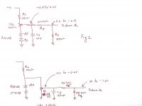
Sorry , Connect two red LED instead of one LED and a diode to get 0 t0 -1.2 V at base of Q1. calculation mistake.Then Voltage across VR1 is -3.6V and Q1 base voltage can vary between 0 to -1.2 V
Last edited:
Yes, XRK, but take real care with the pinouts.......
Hugh
2N5401 is EBC so twist legs 2&3 to use in place of KSA992 ECB
2N5551 is CBE so mirror flip to use in place of KSC1845 ECB
MJE350 is ECB so is pin compatible with KSA1381
2N5401 is EBC so twist legs 2&3 to use in place of KSA992 ECB
2N5551 is CBE so mirror flip to use in place of KSC1845 ECB
MJE350 is ECB so is pin compatible with KSA1381
Ok, so I got that wrong....
I mean, who shows the pin diagram for a transistor with the round back facing you? Everyone else has the flat facing the reader.
https://www.fairchildsemi.com/datasheets/MM/MMBT5551.pdf
Last edited:
Well, I changed out all BJT's, pulled the 2SC5200 and measured its Vbe and Vce and it matches a pristine unit at 0.594v ea. I replaced th IRFP240 (although the old one measured ok). I replaced all 1N400x diodes, the 12v zener, two of the 470uF caps, checked to make sure the trim pots were good, checked the resistance of all resistors,... and it still doesn't work. The board is cursed and I am stopping. It simply does not want to work again because I basically have completely flushed it with new parts.
What else could be wrong? It draws 1.35 amps current across 10R safety resistor when I plug it in. Movement of bias pot does nothing.
🙁
I will salvage the MOSFET and the Toshiba BJT, my hand wound inductor, and toss the rest and call it a night. Sad, but I give up...
What else could be wrong? It draws 1.35 amps current across 10R safety resistor when I plug it in. Movement of bias pot does nothing.
🙁
I will salvage the MOSFET and the Toshiba BJT, my hand wound inductor, and toss the rest and call it a night. Sad, but I give up...
Last edited:
Well, I changed out all BJT's, pulled the 2SC5200 and measured its Vbe and Vce and it matches a pristine unit at 0.594v ea. I replaced th IRFP240 (although the old one measured ok). I replaced all 1N400x diodes, the 12v zener, two of the 470uF caps, checked to make sure the trim pots were good, checked the resistance of all resistors,... and it still doesn't work. The board is cursed and I am stopping. It simply does not want to work again because I basically have completely flushed it with new parts.
What else could be wrong? It draws 1.35 amps current across 10R safety resistor when I plug it in. Movement of bias pot does nothing.
🙁
I will salvage the MOSFET and the Toshiba BJT, my hand wound inductor, and toss the rest and call it a night. Sad, but I give up...
have you checked wrong value resistors and wrong oriented electro caps? or any bad(short) diode?
reg
Prasi
Ok, so I got that wrong....
I mean, who shows the pin diagram for a transistor with the round back facing you? Everyone else has the flat facing the reader.
https://www.fairchildsemi.com/datasheets/MM/MMBT5551.pdf
I make it my convention to read pin out of to-92's with flat facing me and left to right by "name" and never the pin number. some manufacturers even use different pin numbering. NXP BC-550 1-E, 2-B, 3-C. Still a B-C-E if you follow above convention, but by pin number convention is different to fairchild.
Last edited:
The electrolytic caps and resistors are all the ones that were in place when it was working until I accidentally caused the base pin 3 of the BD139 to touch the +35v rail when trying to measure the voltages on the Vbe multiplier.
I checked for shorts on diodes and replaced two of them for good measure. The little 47uF caps are still original - maybe one of those is bad?
Otherwise - film caps and metal film resistors remaining are safe.
I checked for shorts on diodes and replaced two of them for good measure. The little 47uF caps are still original - maybe one of those is bad?
Otherwise - film caps and metal film resistors remaining are safe.
- Home
- Amplifiers
- Solid State
- Very simple quasi complimentary MOSFET amplifier