XRK,
When an amp is not working, you MUST measure two vital figures if you can:
1. Voltage offset with black probe on ground red on speaker node.
2. Quiescent current; no load, through the upper source resistor.
Then you know HOW BAD it is!
I presume it's pulling current through the rail? If so, disconnect the upper source resistor so the output devices are out of the circuit and then measure voltages all over the remaining active devices and test points as noted by Thimios.
Then we all know HOW BAD, WHERE ITS BAD, and WHY ITS BAD.
Being BAD is just not enough. Once you get through all this you will be in a great position. BTW, I would trace a sharp point between all tracks and pads to remove any unforseen shorts before you switch it on again.
Keep trucking.......
Hugh
I hope I'll be lucky mine will work,fingers crossed
Are you close to finish it?
a few parts missing gonna collect them today
What do you think about Joshvis idea in pos 889?
What do you think about Joshvis idea in pos 889?
Last edited:
The electrolytic caps and resistors are all the ones that were in place when it was working until I accidentally caused the base pin 3 of the BD139 to touch the +35v rail when trying to measure the voltages on the Vbe multiplier.
I checked for shorts on diodes and replaced two of them for good measure. The little 47uF caps are still original - maybe one of those is bad?
Otherwise - film caps and metal film resistors remaining are safe.
If the base of bd139 is shorted with +ve rail ,the following components get damaged immediately due to very low resistance path .Q4(BD139),D7 (3.3V zener or blue LED), Q3 (ksa1381), Q2 (ksc1845) and R24 (10 ohm). you already replaced all transistors, So please check D7 and resistor R24
The electrolytic caps and resistors are all the ones that were in place when it was working until I accidentally caused the base pin 3 of the BD139 to touch the +35v rail when trying to measure the voltages on the Vbe multiplier.
I checked for shorts on diodes and replaced two of them for good measure. The little 47uF caps are still original - maybe one of those is bad?
Otherwise - film caps and metal film resistors remaining are safe.
Hello
I've been following this thread a bit and this will be likely my one and only post. I have had the above happen on amp modules I've built and tested, including one just recently. When something gets accidentally shorted it does bizarre things that are hard to find.
One thing I do after all else fails is to start measuring resistors. Slowly go about testing them on the board to be sure each one still has the proper resistance. Dead resistors do not show damage in these situations but when you touch the probes across them they show no connection.
Do you work with a magnifying lamp or magnifying glass? This is a good way to check the board.
In these situations some little thing is causing all the frustrations. Finding that little thing is hard. Correction is usually quite easy.
After all this, follow Hugh's advise in his post #901.
XRK,Hello
Do you work with a magnifying lamp or magnifying glass? This is a good way to check the board.
++ if possible use a bright led torch from the component side of PCB to check for shorts between pads and also for discontinuity in a track. Also you need to clean that PCB with CCl4 to get rid of the soldering crud.
... Movement of bias pot does nothing.
Sad, but I give up...
The only faulty components I have ever had was a pot, twice.
Now I always check for the clicking noise a full scale and measure that it working.
regards
Thanks for all the support guys. I may give it a go one more time having heard nice encouragement and tips like this.
@joshvi: where is R24?
I will try to clean with a toothbrush and alcohol.
Check all resistors.
Replace C7 as it was reverse biased.
Check that pot VR2 actually works.
Measure voltage at speaker out.
Measure quiescent current at R20 and R21.
Run a sharp point between traces and pads (many of which are lifted/damaged and had to be grafted with a jumper to next nearest solid point). This particular board is fragile with poor adhesion between copper foil and board as the suction force from my spring loaded desoldering sucker has enough force to lift the pad up with the hot solder.
This particular board is fragile with poor adhesion between copper foil and board
it´s home made, or from board manufacturer?
This is going to sound funny but my favorite cleaning agent is WD-40 and water. Spray some WD-40 and scrub with a tooth brush. Spray it off with some warm water and blow dry. Clean as a whistle. Alcohol always seems to leave the board sticky.
Thanks for the WD40 tip - I have some and will give it a shot. Probably mineral spirits may do a similar thing then.
Hi XRK (what is your name???),
Do you have a measurement on the emitter resistor, 10R, of Q2?
Please measure the output offset and the quiescent!
Finally, measure the voltage wrt ground on the base of Q1.
It should be easy to fix this........
Do you have a measurement on the emitter resistor, 10R, of Q2?
Please measure the output offset and the quiescent!
Finally, measure the voltage wrt ground on the base of Q1.
It should be easy to fix this........
Hi Hugh,
I just go by X around here🙂
Thanks for the positive energy and encouragement. I will try again in a few hours. Just got back from work. I am a bit jaded now so I don't personally think this amp is fixable anymore. It may be the damaged traces that is causing so many problems.
But I will report back the requested info.
She sings again finally...
The board had major foil liftoff/breakage issues. I used Ronson lighter fluid and a toothbrush to clean all the flux gunk up. It evaporates without residue and once clean, I could see the damaged pads much more clearly. I went in and used a magnifier and continuity tester to check each pad and trace. There were nearly a dozen broken pads that separated from the board and sometimes the trace it was connected to. No wonder replacing parts won't fix it. I replaced each broken pad with a jumper to the next nearest point. I am able to get 0mV DC offset adjustment now. Once warmed up it is pretty stable.
Here is all the rework required to get this board back to playing music:
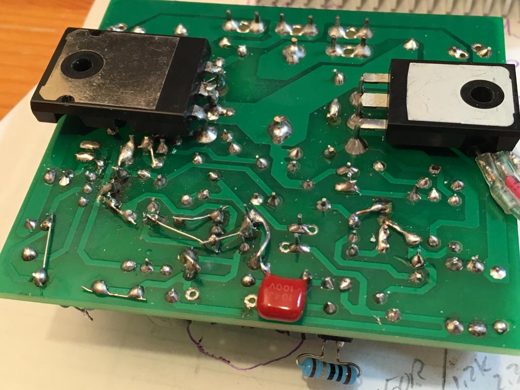
So the amp works fine with 2N5501 and 2N5401 and MJE350's. I wonder if the change to the new input transistors allows the DC offset to cross zero volts now as Aksa had suggested that it would. I am running 100mA quiescent current. These transistors are way more readily available and less expensive. You have to cross the pins 2 & 3 on the 2N5501 and 2N5401 though to use on this board.
So unit 1 is now working again, but I had subsequently fried unit 2 and will have to go through a similar process to fix. Another night though. I will stop while I am ahead.
The board had major foil liftoff/breakage issues. I used Ronson lighter fluid and a toothbrush to clean all the flux gunk up. It evaporates without residue and once clean, I could see the damaged pads much more clearly. I went in and used a magnifier and continuity tester to check each pad and trace. There were nearly a dozen broken pads that separated from the board and sometimes the trace it was connected to. No wonder replacing parts won't fix it. I replaced each broken pad with a jumper to the next nearest point. I am able to get 0mV DC offset adjustment now. Once warmed up it is pretty stable.
Here is all the rework required to get this board back to playing music:
So the amp works fine with 2N5501 and 2N5401 and MJE350's. I wonder if the change to the new input transistors allows the DC offset to cross zero volts now as Aksa had suggested that it would. I am running 100mA quiescent current. These transistors are way more readily available and less expensive. You have to cross the pins 2 & 3 on the 2N5501 and 2N5401 though to use on this board.
So unit 1 is now working again, but I had subsequently fried unit 2 and will have to go through a similar process to fix. Another night though. I will stop while I am ahead.
Attachments

Last edited:
I guess we need to know if x made his work with Hugh's values. Mine works just fine but Hugh feels it can be better.
- Home
- Amplifiers
- Solid State
- Very simple quasi complimentary MOSFET amplifier