Hi Hugh,
I will buy some KSC1845 ( only 6.80 € for 100 at MOUSER ) therefor I will not need to twist the legs in the future 🙂
I have replaced the two red led with 2N4148 as you suggested and I have been able to trim the offset down to few mV 😎
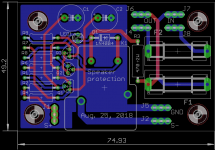
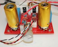
Now the Quasi is playing since one hour on a cheap loudspeaker without box. i fixed the bias at 50 mV = 150 mA and the heatsink is only a little warm at 44°C. Before to connect it on better equipment, I will build a small protection module for which I have received the PCB yesterday (see picture).
I cannot comment yet in detail about the sound because I did not use a preamplifier and with the input directly connected to a CD player, the output power is not very high, even if I have increased the power supply to +/- 41 VDC, but it look very promising...
Best regards,
Marc
I will buy some KSC1845 ( only 6.80 € for 100 at MOUSER ) therefor I will not need to twist the legs in the future 🙂
I have replaced the two red led with 2N4148 as you suggested and I have been able to trim the offset down to few mV 😎
Now the Quasi is playing since one hour on a cheap loudspeaker without box. i fixed the bias at 50 mV = 150 mA and the heatsink is only a little warm at 44°C. Before to connect it on better equipment, I will build a small protection module for which I have received the PCB yesterday (see picture).
I cannot comment yet in detail about the sound because I did not use a preamplifier and with the input directly connected to a CD player, the output power is not very high, even if I have increased the power supply to +/- 41 VDC, but it look very promising...
Best regards,
Marc
Attachments
Hi chat72, Hi avtech23,
Yes, I can publish the Gerber files, but I prefer to finish the test and give a correct description of the part used before to make it public to let the user's to build it without the small modifications I had to make 😕
This was a project made by Ranchu, Hugh and many other participate, Prasi send me his file to save design time in making the PCB and even improved it, it is really a job of several people 😀
As you understand I prefered to make a PCB which will fit in an existing box than to make a box around a PCB because I am not very good in mechanic
Best regards,
Marc

Yes, it play music non stop since this morning but the level is not very strong with the amplifier connected to the output of a CD player (about 2 V in general). When I use a tube amplifier like the EL34 Baby Huey, I need to add a pot to reduce the volume to a listenable level and it is a only 35 to 40 W amplifier ?
Is there a way to have more amplification or did I chose a wrong value in one of the resistors ? What is the normal input level and the maximum level 5V, 10V ? May be I will use it with a tube preamplifier like the one I have designed recently, see picture.
Beside this point the quality look very good but I cannot comment too much because I have only one channel connected to a "naked" loudspeaker, until I have finished my protection module...
Best regards,
Marc
Attachments
Hello Marc,
Gain is almost 23. So you should have quite a bit of power.😕
I can't remember people ever complained lack of gain.
Hmm, what's happening? I will study schematic in more detail when I get time, you have been keeping me busy with GB.. can you post the bom you used?
Regards
Prasi
Gain is almost 23. So you should have quite a bit of power.😕
I can't remember people ever complained lack of gain.
Hmm, what's happening? I will study schematic in more detail when I get time, you have been keeping me busy with GB.. can you post the bom you used?
Regards
Prasi
Last edited:
Marc,
If it is not much gain, there might be an issue with the feedback resistors.
Please paste in your schematic; it should be 1.8k (series fb) and 82R (shunt fb).
Hugh
If it is not much gain, there might be an issue with the feedback resistors.
Please paste in your schematic; it should be 1.8k (series fb) and 82R (shunt fb).
Hugh
Hello Hugh,
I have used the schematic from Prasi to design the PCB, but i took the value from the schematics made by DACZ in Aug 22, 2016 (REV 2).
R9 = 1.5k 2W and R8 = 68 ohm
I don't have 1.8k with more than 0.6W power, can I reduce R8 to 56 ohm ?
Marc
PS: When I check the part on the PCB I was mystified by the print on R9 : 1802 I was thinking it was the value, but it was probably the date code
Attachments

Marc,
With 1.5k and 68R for fb network you have a gain of (1500+68)/68= 23. This should be OK for most digital sources. There is no requirement for using a 1W resistor at 1.5k, but there are some advantages using a carbon resistor, half watt is enough. Carbon resistors alter the harmonic profile of the output, and give a little more H2, like a tube amp which usually use carbon resistors too.
If you want a bit more gain, say 32.9, you could decrease the shunt resistor from 68R down to 47R - or 56R for an intermediate gain of 27.8. No other changes to the amp if you do not change the 1k5 series fb resistor; changing this resistor will affect offset and may need different voltage references; red, or even green leds.
How is the sound?
Hugh
Hugh,
I cannot give too much comments about the sound because it is good but is not strong enough to give a real appreciation. I changed the loudspeaker for a better one and the sound is clear, no noise but only may be 1 or 2 W !
Did you think that the bad connection of the 2N5551 could have killed the 2N5401 or the 2SA1381 ?
Thanks for helping a tube guy 🙂
Marc
Marc,
There is something wrong here. Check all resistors in the input and fb networks and check particularly the resistor from voltage ref to base of Q1. I think you may have a resistor issue.
Worth a good check. Are both channels behaving the same?
HD
There is something wrong here. Check all resistors in the input and fb networks and check particularly the resistor from voltage ref to base of Q1. I think you may have a resistor issue.
Worth a good check. Are both channels behaving the same?
HD
Hugh,
I have built only one channel, I want to finish to test it before I build the second one... I will measure all resistors and come back.
By the way is there a schematic with the voltage values on key locations, it seem I have seen that somewhere in the thread ?
Marc
I have built only one channel, I want to finish to test it before I build the second one... I will measure all resistors and come back.
By the way is there a schematic with the voltage values on key locations, it seem I have seen that somewhere in the thread ?
Marc
Yes, thanks Colin, that is the reference, #2246 on page 245. But note that schem indicates 32V rails, yours may be higher.
What you really need are the bias points for the output stage, and the reference voltage for the input transistor base, shown here at -1.95V.
My thanks to Bangla H!
HD
What you really need are the bias points for the output stage, and the reference voltage for the input transistor base, shown here at -1.95V.
My thanks to Bangla H!
HD
Last edited:
Thanks,
I have found it and the voltages look OK, a little higher than indicated but since I am working with 40 VDC power supply instead of 32 VDC I think it is normal...
What I am thinking now is that Q3 could have been destroyed by the wrong connection of Q2 ? Unfortunately while I was connecting a scope to see the the signal at each stage, I have made a short circuit and R20 became so hot that the solder on the pin melt and I burn my finger
Now nothing work and I think I may have destroyed the output transistors as well
Lesson learned, I will add my small protection module with fuses before to continue the test 🙁
If I cannot go ahead, I will wait to receive the KSA1845 Wednesday or Thursday and build the second channel to see if it work flawlessly ?
Cheers,
Marc
Attachments

Marc, did you test the dc protection circuit ? if so on what voltage does it operate, positive and negative ?
Hi Jan,
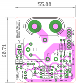
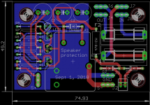
No, I didn't test it yet, but after your question, I have seen that I posted an obsolete schema and layout, I have added the AC voltage input to include the power on delay and to power it from AC instead of the +42 VDC of the Quasi, here is the final version of the protection module 🙂
Prasi made also a PCB that can be fixed directly on the panel mount speaker binding post ( My MOSFET amplifier designed for music. ) see post 744.
This is a very classical schema, I didn't invent it, in fact I use it since about 10 years in the MyRef LM3886 excellent amplifier designed By Mauro Penesa, and it has always worked very well therefor there should be no problem 🙂
The voltage can be adapted with R3 and you need 24 VDC for the relay !
Rgds,
Marc
Attachments
Marc, I have not tried this circuit, but do test it before you install it. Positive and negative voltage, I am not sure what would be a good voltage to activate the circuit, I would think about or around 1.5 to 2 volt. To use a separate supply to power the protection is a good option.
Marc, I have not tried this circuit, but do test it before you install it. Positive and negative voltage, I am not sure what would be a good voltage to activate the circuit, I would think about or around 1.5 to 2 volt. To use a separate supply to power the protection is a good option.
- Home
- Amplifiers
- Solid State
- Very simple quasi complimentary MOSFET amplifier