Hello Marc,
Not yet. Customs and Postal system can be a bit slow here once it arrives in India.
Which capacitor you are using for C4?
regards
Prasi
Not yet. Customs and Postal system can be a bit slow here once it arrives in India.
Which capacitor you are using for C4?
regards
Prasi
It is a Nichicon Polymer Capacitor 1000 uF 16V : RNL1C102MDS1PX Nichicon | Mouser France
Is it OK ?
Thanks
Marc
Is it OK ?
Thanks
Marc
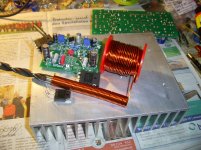
Spring Coil Wire
😛
Hi Marc 1,32mm should be good choice.
How many times the amp will play like disco/party level? 🙂
First i make wire a bit straight-line, so its better wounding around.
Press the wire with thumb to drill and a bit drawing the wire- handwork.
TME is good to use here, i think they also have polymer caps.
Regards.
Attachments
Hi Bangla,
Tanks for the tip, I have received the suggested wire from TME and made my coil as you can see on the picture, it is not too bad for a first try
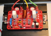
Since the board is now completed I started the test with +/- 25 VDC and I started to have problems, if I was able to adjust the bias to 35 mV, I couldn't adjust the offset which is at -22 V !!! Beside that the resistor in the emitter of the 2SC5200 become very hot quickly and I stop the test 😡
Did you think that the bipolar transistor is fried ? I am not experimented at all with semiconductors, tubes are more resistant, but before soldering a new one, I would like to get some recommendation since the problem could come from an other part, I am surprised that a power transistor could go away so fast ?
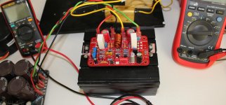
As you can see on the second picture I used two power resistors in serie (4.7 + 3.3 ohms) to simulate a speaker of 8 ohms and i made a short circuit on the input.
Thanks,
Marc
Tanks for the tip, I have received the suggested wire from TME and made my coil as you can see on the picture, it is not too bad for a first try
Since the board is now completed I started the test with +/- 25 VDC and I started to have problems, if I was able to adjust the bias to 35 mV, I couldn't adjust the offset which is at -22 V !!! Beside that the resistor in the emitter of the 2SC5200 become very hot quickly and I stop the test 😡
Did you think that the bipolar transistor is fried ? I am not experimented at all with semiconductors, tubes are more resistant, but before soldering a new one, I would like to get some recommendation since the problem could come from an other part, I am surprised that a power transistor could go away so fast ?
As you can see on the second picture I used two power resistors in serie (4.7 + 3.3 ohms) to simulate a speaker of 8 ohms and i made a short circuit on the input.
Thanks,
Marc
Attachments
Hi Marc.
Only my little two cent....😕. I do setup without load resistors and mostly not shorted input.
Don't know if that is the reasen you have oszillation- the hot resistor shows that.
Thimios has done first tests to right measuring and Test Point voltages here in thread, because 2 LED was to much forward voltage to come to offset.
I see you have two red LED in use- only one is suggested.
VR1- 500R; VR2-1k
R4 is not used.
You not use blue LED?- in 3,3V zener- is ok.
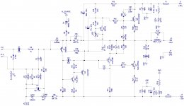
I add schemas for help, more is over my head, sorry that i don't could do more.
Hopefully other give some attention to help.
The zip schema is what i use and it worked.
Regards.
Only my little two cent....😕. I do setup without load resistors and mostly not shorted input.
Don't know if that is the reasen you have oszillation- the hot resistor shows that.
Thimios has done first tests to right measuring and Test Point voltages here in thread, because 2 LED was to much forward voltage to come to offset.
I see you have two red LED in use- only one is suggested.
VR1- 500R; VR2-1k
R4 is not used.
You not use blue LED?- in 3,3V zener- is ok.
I add schemas for help, more is over my head, sorry that i don't could do more.
Hopefully other give some attention to help.
The zip schema is what i use and it worked.
Regards.
Attachments

Hi Bangla,
Yes, you are right : it is not necessary to put a load on a transistor amplifier because there is no output transformer, it's a old habit for me with tube amplifier where you MUST put a load, but even with a load the Quasi should be OK
I shorted the input to be sure to have no signal...
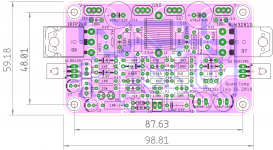
I have used prasi schematic below and he has improved my PCB like for the Baby Huey (bigger pads, larger track, round corner, etc...) but there is nothing special. I made an other PCB because I wanted to make a smaller high to fit the board in a 60 mm inside side panel ( Boitier DIY 100% Aluminium avec dissipateur thermique 271x226x70mm - Audiophonics ) 🙂
I have the two red LED and I have measured 3.4 V which seem OK, when I do not use a load the resistor is not warm and the transistor is always cold. I see two possibilities either the 2SC5200 that I am using instead of the MJW3281 is in short circuit or it is driven always on ? I am using 5.1 ohm instead of 2.2 ohm for R 17 but I don't think it is a problem since XRK971 use 10 ohm ! I will continue ti check
Thanks for helping,
Marc
Yes, you are right : it is not necessary to put a load on a transistor amplifier because there is no output transformer, it's a old habit for me with tube amplifier where you MUST put a load, but even with a load the Quasi should be OK
I shorted the input to be sure to have no signal...
I have used prasi schematic below and he has improved my PCB like for the Baby Huey (bigger pads, larger track, round corner, etc...) but there is nothing special. I made an other PCB because I wanted to make a smaller high to fit the board in a 60 mm inside side panel ( Boitier DIY 100% Aluminium avec dissipateur thermique 271x226x70mm - Audiophonics ) 🙂
I have the two red LED and I have measured 3.4 V which seem OK, when I do not use a load the resistor is not warm and the transistor is always cold. I see two possibilities either the 2SC5200 that I am using instead of the MJW3281 is in short circuit or it is driven always on ? I am using 5.1 ohm instead of 2.2 ohm for R 17 but I don't think it is a problem since XRK971 use 10 ohm ! I will continue ti check
Thanks for helping,
Marc
Attachments
Hi Marc.
It's clear as tube guy...a load.
Please look to added eagle schema from other Marc- only one green LED- that point should only go to 1,8-2V to set an offset, if i remind right.
Thimios measurements are very careful done and shows another V point between Q6 Gate
and Q5 Base- i have measured for own control 5,1V.
Don't know where better Experts are today?- tired from summer heat? ;-)
Ranchu- Father of thread or Thimios- experienced, could help better.
Hope you can solve problems, cross fingers.
Nice custom pcb job- i know you experienced if i look to very clever and popular Baby
Huy.
Regards
Hello Marc,
The only differences I see from latest schema (Dacz) and yours are
1. instead of 500R, bias trimmer is 1k
2. instead of 2nos. red led's, 2nos. 1N4148 or a single green LED
Regards
Prasi
The only differences I see from latest schema (Dacz) and yours are
1. instead of 500R, bias trimmer is 1k
2. instead of 2nos. red led's, 2nos. 1N4148 or a single green LED
Regards
Prasi
Hi Marc,
Please measure R9. How much is across it? Then measure the base to emitter of T1, is should be 0.6-0.65 volts, no more.
Be sure to have T1 pnp, if its a npn it will really screw things up.
Hugh
Please measure R9. How much is across it? Then measure the base to emitter of T1, is should be 0.6-0.65 volts, no more.
Be sure to have T1 pnp, if its a npn it will really screw things up.
Hugh
Hi Hugh,
Thanks for helping me 🙂
Yes T1 (Q1 on my PCB) is a PNP = 2N5401. The power supply is +/- 30 VDC and the output is - 27.5 VDC, the offset trimmer has no effect at all !!!
The voltage across R9 is about 7 VDC and it is not stable, it is slowly increasing when the amplifier warm up ?
The Vbe of T1 = -10 V and slowly increasing too 😡
For info the Vbe of Q7 is 0.631 V and it is stable...
Cheers,
Marc
Voila, Marc, replace the 2N5401 pnp Q1 and be very careful to have the pinout correct.
The other parts seem fine.
Check also the diode across base/emitter of Q1, be sure to have it the right way in place. If it is reversed, it will destroy the DC conditions in the amp.
I think Q1 is broken!!
Hugh
The other parts seem fine.
Check also the diode across base/emitter of Q1, be sure to have it the right way in place. If it is reversed, it will destroy the DC conditions in the amp.
I think Q1 is broken!!
Hugh
Last edited:
Hi Hugh,
I have changed Q1 but this does not solve the problem 😡
I checked the transistor and it was OK. its hfe was 162, Ic 1.5 mA and Vbe 0.635 V
I also rechecked all solder and cleaned the PCB... The diode is OK but when I checked the 3.3 V zener, I measured only 2.6 V ? I put the picture of the board may be you can see somethings wrong but I have not seen error yet...
The voltage across the red diodes is 3.45 V, I have tried to put one in short circuit to have only 1.7 V but that changed nothing 😕
I am really lost, tubes are much easier for me, even if sometimes 400 V wake up you 🙂
Thanks again for help,
Marc
Attachments

Marc,
What is voltage wrt ground on the:
1. Base of Q1
2. Emitter of Q1
3. Collector of Q1
4. Output (do not connect speaker, leave it unconnected)
Hugh
What is voltage wrt ground on the:
1. Base of Q1
2. Emitter of Q1
3. Collector of Q1
4. Output (do not connect speaker, leave it unconnected)
Hugh
Hi Hugh,
You didn't sleep in Australia ?
Here are the voltage :
Base Q1 = -20.3 V slowly decreasing
Emitter Q1 = -21.6 V slowly decreasing
Collector Q1 = -30.17 V stable
Output is not connected, if I connect it R21 become very hot...
Marc
You didn't sleep in Australia ?
Here are the voltage :
Base Q1 = -20.3 V slowly decreasing
Emitter Q1 = -21.6 V slowly decreasing
Collector Q1 = -30.17 V stable
Output is not connected, if I connect it R21 become very hot...
Marc
Hugh,
i found the problem 😀
Q2 was designed on the PCB for a KSC1845 and I used a 2N5551 and of course some one in the past decided the the pinout for transistors will be different in Japan than in Europe or in USA (see attachement) 😡
I will cross the legs of Q2
I hope after that it will be OK.
Good night,
Marc
Attachments
Yes, that was the problem 😀
Now I have -1.26 VDC on the output but I cannot go lower, if I make a short circuit on one of the red LED I go up to - 0.46 VDC...
Bias is at 40 mV which mean about 120 mA, the power transistors are not warm yet.
I will continue test with the 8 ohm load...
Rgds
Now I have -1.26 VDC on the output but I cannot go lower, if I make a short circuit on one of the red LED I go up to - 0.46 VDC...
Bias is at 40 mV which mean about 120 mA, the power transistors are not warm yet.
I will continue test with the 8 ohm load...
Rgds
Wonderful Marc, C1845 and 5551 have very different pinouts - good find, it is difficult to find pinouts issues.
C1845 is a very good VAS I suggest you find one because they have very low Cob and high beta.
Just arise from sleeping you are correct!
To get offset you must play with the led voltage reference. I would rep,lace the single red led with two series 4148 diodes; that gives you 1.3V rather than 1.6V for re led and it should bring it up to 0mV offset.
HD
Last edited:
Hi Marc,
Is it possible to get Gerber file for your layout, I like the idea of small narrow PCB, so it can be mounted to a slim case.
Regards,
Chatchai
Is it possible to get Gerber file for your layout, I like the idea of small narrow PCB, so it can be mounted to a slim case.
Regards,
Chatchai
Yes, that was the problem 😀
Now I have -1.26 VDC on the output but I cannot go lower, if I make a short circuit on one of the red LED I go up to - 0.46 VDC...
Bias is at 40 mV which mean about 120 mA, the power transistors are not warm yet.
Glad you found the problem Marc.
I just checked my boards (irfp250+2sc5200) and realised I assembled one with blue LED (instead of 3.3vZ) + green LED and one with blue LED + 1n4004 🙄
I had an easy time adjusting the offset and bias on both boards though.
Last edited:
- Home
- Amplifiers
- Solid State
- Very simple quasi complimentary MOSFET amplifier