AJT: did you try adjusting tail currents?
RC: Yes, increasing big ccs current slightly reduces offset but only slightly, from .3 to .25v
Increased driver stoppers to 220r and the problem persists.
Now I will reduce feedback and see what happens
AJT: we have progress, you are on track now, can you post a pdf version of you schematics, these tired old eyes are hard up looking at your simulation pictures...
i remember i also asked you the polarity of the 0.3 mV,? is it positive or negative?
RC: Reduced feedback and oscilation remains now at 250khz
Running out of ideas
The offset is positive
I have 0.3Vdc and 10Vac at 250khz
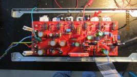
The zobel resistor allready changed color because of the heat
RC: Yes, increasing big ccs current slightly reduces offset but only slightly, from .3 to .25v
Increased driver stoppers to 220r and the problem persists.
Now I will reduce feedback and see what happens
AJT: we have progress, you are on track now, can you post a pdf version of you schematics, these tired old eyes are hard up looking at your simulation pictures...
i remember i also asked you the polarity of the 0.3 mV,? is it positive or negative?
RC: Reduced feedback and oscilation remains now at 250khz
Running out of ideas
The offset is positive
I have 0.3Vdc and 10Vac at 250khz
The zobel resistor allready changed color because of the heat
I killed the oscillation by temporarily placing a big cap over the feeback resistor that now is 33k.
this way I can measure voltages without fear of overheating.
this way I can measure voltages without fear of overheating.
offset is positive means reduction of tail currents is to be done,
you can do this two ways, via small ccs, or the big ccs...
either way, one or both needs reduction in current,
via increased value of emitter resistors...
again my recommendations are:
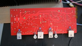
1. remove the variable pot at emitters of the top current mirrors.
hust two 220 ohms resistors and you are done...
2. small ccs, put emitter resistors in series with a fixed resistor...
you can use an off board variable port to adjust bias and then
when the offset is trimmed to 0 volts, you can replace that with a resistor
of the nearest standard value...
you can do this two ways, via small ccs, or the big ccs...
either way, one or both needs reduction in current,
via increased value of emitter resistors...
again my recommendations are:
1. remove the variable pot at emitters of the top current mirrors.
hust two 220 ohms resistors and you are done...
2. small ccs, put emitter resistors in series with a fixed resistor...
you can use an off board variable port to adjust bias and then
when the offset is trimmed to 0 volts, you can replace that with a resistor
of the nearest standard value...
Do the 220 ohm emiter resistors in the mirror help tame oscilation ?
In my sim reducing small ccs current really reduces offset but current in the input fets will also be reduced taking those away from my 4mA target (I am using 5mA Idss fets so I run those at 80%)
In my sim reducing small ccs current really reduces offset but current in the input fets will also be reduced taking those away from my 4mA target (I am using 5mA Idss fets so I run those at 80%)
Do the 220 ohm emiter resistors in the mirror help tame oscilation ?
i do not think so, but the reason those current mirrors are there is to
decrease the trannie transconductance... those current mirrors serves as
load to the cascode trannies,
the jfets can be run at lower currents, that should not be an issue...
Hey RC, if you put a second symmetrical diffamp between the cascode jfet input stage and the vas, you have an AEM6000, which I admit I'm rather partial to. It's got gobs of open-loop gain and plenty of speed.
so all this is only simulations and not an actual amp?
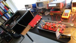
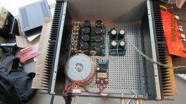
Off course there is an amp.... I designed the schematic based on the HB but modded it to use input jfets and output laterals.
Spent a lot of time and money to build these things and would really like to have them working.
Off course there is an amp.... I designed the schematic based on the HB but modded it to use input jfets and output laterals.
Spent a lot of time and money to build these things and would really like to have them working.
you have deviated a lot from the hb theme....
While searching for sources of oscillations I found this paper that gave me an idea.
Maybe the cascode in the LTP is where the collpits is.
C6 is not refered to GND and as there is no zener to bias the cascode I now see this cap does not decouple noise.
I will remove it first.... then if needed I will place a cap from the cascode bases to gnd
Maybe the cascode in the LTP is where the collpits is.
C6 is not refered to GND and as there is no zener to bias the cascode I now see this cap does not decouple noise.
I will remove it first.... then if needed I will place a cap from the cascode bases to gnd
Attachments
Removed C6 and offset went down from 0.3v to 30mv ... manageable....
I still have oscilation but now 6.4Vpp at 2Mhz
I still have oscilation but now 6.4Vpp at 2Mhz
Placed a 1u cap between the bases of the LTP cascodes and signal GND and oscilation disapeared from the scope (RIGOL DS1074) and offset went down to 6mV.
Now will revert to the "normal" drivers MJE....
Now will revert to the "normal" drivers MJE....

initially I killed amplification because I used a big cap on the vas.... now it works as expected
Offset is now 3mv. Sounds good on my bench system. I have too much turn on voltage on the output.... needs turn on delay...
Cool! I wonder how it compares to the normal Honey Badger.Offset is now 3mv. Sounds good on my bench system. I have too much turn on voltage on the output.... needs turn on delay...
You are using old and probably bad simulation models. I suggest you delete them and use these:
CordellAudio.com - SPICE Models
CordellAudio.com - SPICE Models
- Status
- Not open for further replies.
- Home
- Amplifiers
- Solid State
- Very HQ power amplifier (Assemblage VII)