Rudi,
If possible count me in for a complete kit inc matched LDRs. Maybe next build?
Thanks
Anjum
If possible count me in for a complete kit inc matched LDRs. Maybe next build?
Thanks
Anjum
Great. That's what I was planning on. Could you also include 2 remotes in my order, whenever they are shipped. I just as soon get something I know is compatible with the Pre and will work immediately....Rick: this PRE will be the perfect mate for your "BlackBeauty - SYMASYM" (see attached image 2 of my own SYMASYM).
The shown PRE (the current version) uses a motorized potentiometer.
The new, offered version will replace it by a digitally controlled potentiometer.
Best regards - Rudi_Ratlos
Thanks,
Rick
May I join the team for 1 kit? Perhaps the increasing number of those who want this new version will force Rudi to change his mind. We have to reach the critical mass!
Emil
Emil
Emil: I am sorry! I have already ordered the PCBs (10 pcs.), and all of them are assigned!
Best regards - Rudi_Ratlos
Best regards - Rudi_Ratlos
Rudi,
Do you have a source for the 16-conductor cable with the plugs on each end, or do you fabricate your own? I know the length would be dependent on the internal design and physical layout of the modules, but was just curious. I found a ready-made one on eBay for my original Pre, but that was the last one offered.
Rick
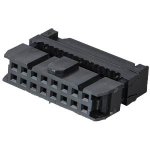
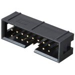
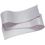
Thanks.Rick, all of the needed parts are available from REICHELT (German distributor).
I squeeze the connector using a small bench vise.
Best regards - Rudi

I have received the PCBs from the etching-company and have already soldered my own copy.
I have shipped METAL's order and am now waiting for him to receive the small parcel, solder the PCB and implement the firmware.
Best regards - Rudi_Ratlos
P.S.: I have 2 spare kits that I will offer, once I am sure that everything works as designed.
I have shipped METAL's order and am now waiting for him to receive the small parcel, solder the PCB and implement the firmware.
Best regards - Rudi_Ratlos
P.S.: I have 2 spare kits that I will offer, once I am sure that everything works as designed.
Attachments
Great stuff!
Okido, if all works well count me in For A complete kit including the matched ldr s 😉
Grz
Taco
Okido, if all works well count me in For A complete kit including the matched ldr s 😉
Grz
Taco
Add me in the the last pcb and kit
If it all works fine count me in for the last extra complete kit including the matched ldr' s😀
If it all works fine count me in for the last extra complete kit including the matched ldr' s😀
I would like a complete kit also. I can send money if needed. I know that there may be none available at this time, but would like to see if enough people are interested to start another group buy if that is ok. Thank You.
Gentlemen, dear DIY-friends of the current group-buy: as I have told you already: I "suffered shipwreck" from my latest "digital-potentiometer attenuation schematic" and had to fall back to an analog potentiometer
(similar as shown in the LDRs' schematic or in George Stantschesffs's design).
The NSL-32SR2 - LDRs proved to be too non-linear with my linear voltage-attenuation schematic.
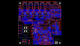
My current "digital solution (MCP42100)" is "too coarse" to do the attenuation and as fallback I will provide you the "old -fashioned" PCBs (look at the attached image), using a dual 100K-log potentioneter to do the LDR-attenuation.
To contemplate with your willingness to wait for the "new RPRE-PCB": I have expanded the PCB (there has been a lot of room left) to include the "Nelson Pass B1-Buffer".
I have ordered a couple of these PCBs several days ago. So: please keep patient!
Best regards - Rudi_Ratlos
(similar as shown in the LDRs' schematic or in George Stantschesffs's design).
The NSL-32SR2 - LDRs proved to be too non-linear with my linear voltage-attenuation schematic.
My current "digital solution (MCP42100)" is "too coarse" to do the attenuation and as fallback I will provide you the "old -fashioned" PCBs (look at the attached image), using a dual 100K-log potentioneter to do the LDR-attenuation.
To contemplate with your willingness to wait for the "new RPRE-PCB": I have expanded the PCB (there has been a lot of room left) to include the "Nelson Pass B1-Buffer".
I have ordered a couple of these PCBs several days ago. So: please keep patient!
Best regards - Rudi_Ratlos
Attachments
Last edited:
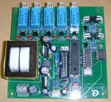
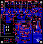
Gentlemen: I have soldered the LDRs on the prototype-PCB (Rick's - PCB - see image1) a hour ago and did some measurements.
The PCB "works as designed".
The input resistance ("impedance" of this passive PRE) varies between 10.4K and 9.8K - which is quite o.k. in my eyes (ears).
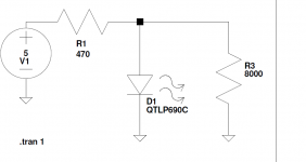
I am currently using the circuit shown in image2 to do the needed (if ever) fine adjustments on the LDRs, giving an input voltage of about 1.9VDC.
I have not yet received the motorized ALPS - dual 100K potentiometer that I have ordered from ebay.
But this will not contribute any problem - I am sure.
I have not yet tested (measured) the "rudimentary" version of the Pass B1 - buffer (which is part of my PCB), since I do not yet have a suitable PSU to power it.
My favourite is a TPS7A4700 - PSU (image 3), but I myself am not able to solder the TPS7A4700 (QFN package).
IMHO the TPS7A4700 is able to compete with SALAS's shunt - PSU to power the low-current B1 - buffer.
I will do my best and send you your letters the course of this week.
Best regards - Rudi_Ratlos
The PCB "works as designed".
The input resistance ("impedance" of this passive PRE) varies between 10.4K and 9.8K - which is quite o.k. in my eyes (ears).
I am currently using the circuit shown in image2 to do the needed (if ever) fine adjustments on the LDRs, giving an input voltage of about 1.9VDC.
I have not yet received the motorized ALPS - dual 100K potentiometer that I have ordered from ebay.
But this will not contribute any problem - I am sure.
I have not yet tested (measured) the "rudimentary" version of the Pass B1 - buffer (which is part of my PCB), since I do not yet have a suitable PSU to power it.
My favourite is a TPS7A4700 - PSU (image 3), but I myself am not able to solder the TPS7A4700 (QFN package).
IMHO the TPS7A4700 is able to compete with SALAS's shunt - PSU to power the low-current B1 - buffer.
I will do my best and send you your letters the course of this week.
Best regards - Rudi_Ratlos
Attachments
Well, Gentlemen,
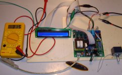
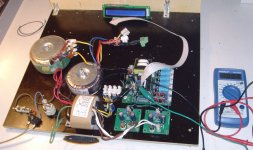
I am currently playing around with the setup shown below (attached image 1).
My 2 x 9VAC / 350mA rated R-Core is driving two LT1763 - PSU - PCBs (the layout of which I have done myself), and I am happily driving the two sections (+10VDC, -10VDC, GND) of Nelson Pass' "rudimentary B1 - buffer".
I will go on with my tests tomorrow and check, if the buffer "behaves as it should".
Best regards - Rudi_Ratlos
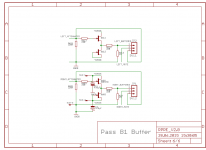
P.S.: Find attached the schematic of "Nelson Pass' "rudimentary buffer".
I am currently playing around with the setup shown below (attached image 1).
My 2 x 9VAC / 350mA rated R-Core is driving two LT1763 - PSU - PCBs (the layout of which I have done myself), and I am happily driving the two sections (+10VDC, -10VDC, GND) of Nelson Pass' "rudimentary B1 - buffer".
I will go on with my tests tomorrow and check, if the buffer "behaves as it should".
Best regards - Rudi_Ratlos
P.S.: Find attached the schematic of "Nelson Pass' "rudimentary buffer".
Attachments
Last edited:
Hi Rudi, i see you use now a logaritmic pot and i remember in the past you used the linear one from Bourns. How is the attenuation curve with the logarithmic pots? Regards, Adrian!
Sent from my iPad using Tapatalk
Sent from my iPad using Tapatalk
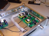
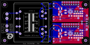
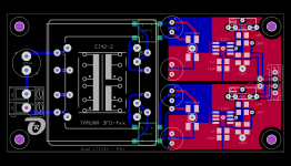
Gentlemen, find attached an image of my current RPRE-build!
It consists of 2 PCBs: the RPRE-V2.2 PCB and a PSU-PCB to power the integrated "Simplistic Nelson Pass B1-Buffer".
The RPRE features:
- 4 selectable input sources
- LDR attenuation
- Integrated Pass B1-Buffer (which can either be activated or by-passed)
- Temperature display
- Interface to a SoftPowerOn - PCB
- 1x16 LCD to show the relevant information
- All functionality can be controlled via an IR remote control unit
- ...
The offered PSU is either a dual symmetric TPS7A4700 based PSU or (in case that you are not able to solder the TPS7A4700 by yourselfor do not know anybody, who will do this for you)
a dual symmetric LT1763 based PSU, which is easy to solder and does a good job as well.
The sizes are: 100 x 100mm for the RPRE-PCB and 50 x 100mm for the PSU-PCBs.
I have 4 (no more!) of each PCBs (RPRE and both PSUs) left.
The RPRE sounds really very nice!
I will provide you:
- the PCBs (cost of a PCB is 5€)
- 2 pairs of matched LDRs (the 2 pairs cost 20€)
- a pre-programmed PIC16F688 µProcessor (cost is 5€)
- a pre-programmed Grande Seki remote control unit (cost is 15.50€)
- Builder's Guide and BoM
If you are interested: please tell me.
Best regards - Rudi_Ratlos
P.S.: The PSU shown on image 1 is my prototype Dual-TPS7A4700 - PSU.
Attachments
- Status
- Not open for further replies.
- Home
- Group Buys
- Versatile and comfortable passive pre-amp