TUO: my passive Pre-Amplifier is able to connect to (to choose between) five - music-sources (by means of the 5 relays on top of the PCB).
Was switching sources using LDR's ever considered? In this fashion the inputs each see their own LDR, and only one is activated at a time to let signal through(and attenuate at the same time).
I'm starting to put together a plan for a dac/pre combo and i'm leaning towards this solution, but i do need a way to switch digital sources into my JP/Subbu DAC, so i'm actively looking for solutions.
yacuza: I have never considered LDRs to replace a relay.
It is already a hard job to find matched LDRs to do the attenuation of the selected signal, and I do not like to make it even more complicated.
I have some problems currently "marrying" the new version of the VCPre with the line buffer.
On the oscilloscope, with no amp connected, the output of the line buffer looks fine, but when I connect it to an amplifier, the music sounds "distorted".
I suspect my very cheap 7818/7918 line-buffer-PSU to be the reason for the distortion and have to wait for the delivery of a more "sophisticated" PSU.
Best regards - Rudi_Ratlos
Gentlemen: please do not misunderstand my last post!
The VCPre itself does a very, very good job - provides the best attenuation that I have ever heard!
The implemented line-buffer is a gem as well, as I have been reported by many of my German DIY-friends!
So it must be due to the poor design of my line-buffer's PSU (+/-18VDC) that the marriage of the two of them does not sound as it shall!
Best regards - Rudi_Ratlos
Rudi,
My VCpre is sounding pretty good, I went with the modified JBIS for the gain. I used Owen's wire power supply board. It is a little overkill but is a nice design that is available, Granted some smt soldering but nothing as small as your regulator.
http://www.diyaudio.com/forums/vend...jects-available-here-bal-bal-se-se-lpuhp.html
Many thanks for a great preamp.
Bill
Gentlemen: please do not misunderstand my last post!
The VCPre itself does a very, very good job - provides the best attenuation that I have ever heard!
The implemented line-buffer is a gem as well, as I have been reported by many of my German DIY-friends!
So it must be due to the poor design of my line-buffer's PSU (+/-18VDC) that the marriage of the two of them does not sound as it shall!
Best regards - Rudi_Ratlos
Rudi, I recommend you try this power supply :
http://www.diyaudio.com/forums/group-buys/75994-scalable-psu-regulator-gb.html
Many years ago when I built an active pre I tried numerous power supplies. This one was by far the standout. Compared to 3 terminal regulators the difference was night and day. Maybe Jens or Bob will give you permission to use it.
Last edited:
Gentlemen, I have connected a Version -1 VCPre to the Calvin-Buffer prototype and measured and listened to it!

http://abload.de/img/ldr005k6qri.jpg
It worked as designed and sounded delicious (even using a 7818 / 7918 PSU)!
Then I ordered one piece of the "All-in-One" (VCPre and Buffer on the same PCB as shown in post #637)) prototype PCB.
I soldered the PCB, it did not work, I managed to find the error (in the interface between VCPre and buffer - I have mixed input and output tracks), but was unable to fix the issue.
I will therefore not offer the "All-in-One" PCB.
On the one hand: it is very (too) complex to troubleshoot, in case you made an error, on the other hand: if you are going to build an integrated amplifier that has a suffienctly high input impedance (>20K, f.e. the SYMASYM),
you do not need a buffer at all.
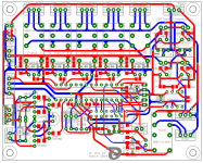
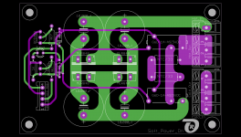
I will instead offer two distinct PCBs (see the attached images):
- Buffer (the PCB-size is 50x60mm)
This is a Stereo-Buffer based on Calvin's buffer and has a 3 - connector - interface: Power, 2-channel Input and 2-channel Output
- Passive Pre-Amplifier (the PCB size is 100 x 80mm)
It is equipped with LDR-attenuation, LCD-interface, 5 source input selection, mute, SoftPowerOn interface, ..., everything can be remotely controlled
I will order 10 pcs of each of the PCBs this weekend - and restart again.
I am quite sure that everything will work this time.
As PowerSupply I will use LM317 / LM337 circuits (already ordered), but I do have an eye on building a PowerSupply based on TI's TPS7A - regulators as well (even on WINEDS's recommendation).
I will keep you informed.
This is DIY.
Best regards - Rudi_Ratlos

http://abload.de/img/ldr005k6qri.jpg
It worked as designed and sounded delicious (even using a 7818 / 7918 PSU)!
Then I ordered one piece of the "All-in-One" (VCPre and Buffer on the same PCB as shown in post #637)) prototype PCB.
I soldered the PCB, it did not work, I managed to find the error (in the interface between VCPre and buffer - I have mixed input and output tracks), but was unable to fix the issue.
I will therefore not offer the "All-in-One" PCB.
On the one hand: it is very (too) complex to troubleshoot, in case you made an error, on the other hand: if you are going to build an integrated amplifier that has a suffienctly high input impedance (>20K, f.e. the SYMASYM),
you do not need a buffer at all.
I will instead offer two distinct PCBs (see the attached images):
- Buffer (the PCB-size is 50x60mm)
This is a Stereo-Buffer based on Calvin's buffer and has a 3 - connector - interface: Power, 2-channel Input and 2-channel Output
- Passive Pre-Amplifier (the PCB size is 100 x 80mm)
It is equipped with LDR-attenuation, LCD-interface, 5 source input selection, mute, SoftPowerOn interface, ..., everything can be remotely controlled
I will order 10 pcs of each of the PCBs this weekend - and restart again.
I am quite sure that everything will work this time.
As PowerSupply I will use LM317 / LM337 circuits (already ordered), but I do have an eye on building a PowerSupply based on TI's TPS7A - regulators as well (even on WINEDS's recommendation).
I will keep you informed.
This is DIY.
Best regards - Rudi_Ratlos
Attachments

Hallo Rudi
I have lost until now 2 times VCPre pcb's and 3 times Symasym to3 pcb's.
Please count me for 2 pcb of VCPrerev.2
Regards
Andreas
I have lost until now 2 times VCPre pcb's and 3 times Symasym to3 pcb's.
Please count me for 2 pcb of VCPrerev.2
Regards
Andreas
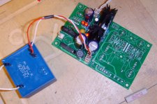
Paul, I built a 5VDC PSU based on the LM317 tracking pre-regulator design yesterday, put a 80 Ohm resistor on its output and measured.
I adjusted the output voltage by means of two red 3mm LEDs, giving a voltage drop of 3.8V; add the LM317 internal voltage drop of 1.25V to it.
The result looks quite promising.
The last digit of the DMM is not changing any more, so the ripple on the output must be smaller than 10µV.
On the right side of the PCB I will build a +/- 18 VDC power-supply (based on LM317/LM337), on the left side I will do a very quick and dirty 8VDC.
Best regards - Rudi_Ratlos
Attachments

What tubes are you all using for isolating the legs of the LDRs? Are these normal shrinking tubes you are using?
The new Iteration of the VCPre looks promising.
Thanks in advance!
Ron
The new Iteration of the VCPre looks promising.
Thanks in advance!
Ron
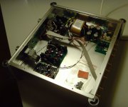
While I am still waiting (since more than 3 weeks) on the current version of my passive pre-amplifier - PCBs to arrive, I have prepared everything to take place into my prototype case (see image below).
From right top to left top you see: the SCHAFFNER - mains - input-filter, the "Soft-Power-On" - PCB (on its right side - it is used to power the connected amplifier; I still need to drill a hole for the used
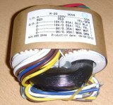
NEUTRIK Power-connector), the mains-DC-filter, a R-Core-transformer (supplying 2x18VAC and 2x9VAC), the PSU (which I feel and measure to do a very, very good job, allthough being based
on the "poor (?)" LM3x7 regulators. You have to consider the layout as well; I have even distinguished between input- and output - GND), the buffer and Jean-Paul's DAC.
I will cover the PSU-components on the top of the case by some kind of ALU-L - profile, covered with µMetall.
Everything is prepared for the R-PRE - PCBs to arrive.
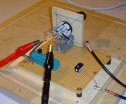
I have received a couple (75) of LDRs and have already measured them!
Well: there are 3-4 quads (6-8 pairs) that match perfectly!
But I need EXCEL to find other pairs (quads) of LDRs that match easily as well; maybe some of them need some kind of fine adjustment by means of the 2 on-board potentiometers! No problem!
I did the measurements of the LDRs by using a LORLIN - rotary switch with 12 resistors (values: from 86KOhm - 680 Ohm), connected to a 5VDC PSU (the 2nd image).
I do not advise you to buy "matched LDR quads" (I am happy to see that he has withdrawn his offer); you will be disappointed by the results (allthough the measurement-protocoll will highly praise it).
Go and buy 10-15 LDRs yourself and measure / match them - or believe in my recommandation / offer.
Best regards - waiting - Rudi_Ratlos
From right top to left top you see: the SCHAFFNER - mains - input-filter, the "Soft-Power-On" - PCB (on its right side - it is used to power the connected amplifier; I still need to drill a hole for the used
NEUTRIK Power-connector), the mains-DC-filter, a R-Core-transformer (supplying 2x18VAC and 2x9VAC), the PSU (which I feel and measure to do a very, very good job, allthough being based
on the "poor (?)" LM3x7 regulators. You have to consider the layout as well; I have even distinguished between input- and output - GND), the buffer and Jean-Paul's DAC.
I will cover the PSU-components on the top of the case by some kind of ALU-L - profile, covered with µMetall.
Everything is prepared for the R-PRE - PCBs to arrive.
I have received a couple (75) of LDRs and have already measured them!
Well: there are 3-4 quads (6-8 pairs) that match perfectly!
But I need EXCEL to find other pairs (quads) of LDRs that match easily as well; maybe some of them need some kind of fine adjustment by means of the 2 on-board potentiometers! No problem!
I did the measurements of the LDRs by using a LORLIN - rotary switch with 12 resistors (values: from 86KOhm - 680 Ohm), connected to a 5VDC PSU (the 2nd image).
I do not advise you to buy "matched LDR quads" (I am happy to see that he has withdrawn his offer); you will be disappointed by the results (allthough the measurement-protocoll will highly praise it).
Go and buy 10-15 LDRs yourself and measure / match them - or believe in my recommandation / offer.
Best regards - waiting - Rudi_Ratlos
Attachments
Last edited:
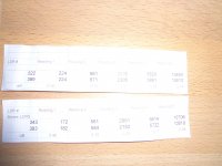
Patrick, it looks like the upper LDRs are a little bit better matched.
So take these as the shunt LDRs (the lower 2 LDRS on the PCB), use the 2nd pair as serial LDRs (the upper 2 LDRs on the PCB) and "match" the serial PCBs by means of the small potentiometer on top of the PCB.
Best regards - Rudi_Ratlos
So take these as the shunt LDRs (the lower 2 LDRS on the PCB), use the 2nd pair as serial LDRs (the upper 2 LDRs on the PCB) and "match" the serial PCBs by means of the small potentiometer on top of the PCB.
Best regards - Rudi_Ratlos
- Status
- Not open for further replies.
- Home
- Group Buys
- Versatile and comfortable passive pre-amp