The old ones are more likely able to take being beat on than new ones, but they do have limits. You might try dialing the screen down to 300 and see if it runs without running away.

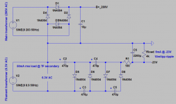
i can suggest a 'double doubler' to generate a sizeable bias voltage from a single 6.3V winding. Each doubler is the 'capacitor input' type, and one generates a positive output, and the other a negative output. Schottky diodes are needed to maximise the total available voltage.
Not appropriate for a 6BQ5 plan, but for bigger/stiffer tubes:
Wire a 120V:12V transformer backward across a 6V winding to make 59VAC and >80V of DC to divide-down in your bias adjusting network.
This added transformer can be very small, <5VA.
The transformer running at half voltage will run cool, quiet, and unstressed.
Wire a 120V:12V transformer backward across a 6V winding to make 59VAC and >80V of DC to divide-down in your bias adjusting network.
This added transformer can be very small, <5VA.
The transformer running at half voltage will run cool, quiet, and unstressed.
If you don't have a transformer for that already, a DC-DC board is cheaper and smaller.
I use 110V for my small amps (into RC and VR75) or 200V for my 6P45S amps (into RC and VR150). You can get one for ~10$.
I use 110V for my small amps (into RC and VR75) or 200V for my 6P45S amps (into RC and VR150). You can get one for ~10$.
In the most recent round of bias attempts, I went with individual 470 Ohm Cathy resistors, 200uF cap bypassed but through a common 50 Ohm to ground. Idle bias sets up ~14-15V. Distortion doesnt measure particularly well, compared to each channel running through a common bypassed 200 Ohm. It took a lot of work to get those in place, including my absolute favorite; detaching without breaking anything the OEM wrapped as foo wires off the flimsy tube socket pins.
I'm sure the lower cathode current is responsible for the higher distortion. I'm chicken to try 390s, the only other values I have 4 of on hand with the B+ at 396V...
Then as fortune would have it, my substitute tube for the one that red plated, red plated. Grabbed the AC cord out of the socket, went for a 2nd power on try - no cathode current at all. Inspection showed off a cracked base...just after lightly bending a couple pins back straight. I put in another, weaker tube that sets up ~13.5V to assure myself the amp at least still plays OK. It does.
So this time (better every loop!) I ordered a "6n18n Vacuum Tube NIB new = 6bq5" from a 100% feedback seller in PR for $13, shipped. With a little luck that one sets up idle bias up more closely with the 3 unburned Sovtek branded survivors. It just may be the middle of next month for that one to show up here.
Being that this is an old amp, and I've seen value failures in the OEM resistors (removed and replaced) is there a good chance the grid stops and / or grid leaks are intermittent? They do all measure OK - with whatever miniscule current a DMM places through. I suppose it could even have happened on the same socket, though I'm unsure.
6P18P is more like EL82 than EL84 but it might work...
https://frank.pocnet.net/sheets/113/6/6P14P.pdf
http://www.nj7p.org/Tubes/PDFs/Frank/113-Soviet/6P18P.pdf
https://frank.pocnet.net/sheets/113/6/6P14P.pdf
http://www.nj7p.org/Tubes/PDFs/Frank/113-Soviet/6P18P.pdf
Both +ve & -ve voltages can be sourced from the same HV winding of a common PT used with vacuum toobz.Maybe you can reference my schematic.
My negative bias is expensive but it is very robust.View attachment 1056567
Refer to #21. No need for a choke in the -ve lead. There is plenty of drop for RC smoothing.
And is inexpensive.
Just replaced the grid stop and grid leak resistors with physically different elements of the same value, on that socket. We'll see if the RP ever shows up again. The construction of the original resistors seems mighty fine quality; alas there were some bad ones as I mentioned, so who knows about the two that just got clipped in half. I've never seen a resistor make a spark when doing this, connected to a grid, in an old amp that's been off for over 24 hours. They appear to be some sort of glass coated ceramic; they used fancy schmancy parts, some failed anyway in time. A pretty ruthless failure too, to go open intermittently and blow up my new tube...and another. Of course, the truth isnt yet known.
So the amplifiers quality of "unmolested" goes out the door, as I work out the component failure bugs. I'd have to replace 'em all, to get component type consistency between stages. That's what you have sometimes, fixing up an old amplifier bought on ebay.
I put a level balancer in the phase splitter, which is just a slightly variable resistor in one of the legs. You can reduce the measured distortion by tweaking it; for the 2nd harmonic at 1 kHz at least you can go through the null as you dial it in. I wonder if the 2nd would be one phase, say "in" on one side of the null, while "out" on the other side. It seems intuitive that would be so.
Cockroft-Walton multiplier off the AC filament transformer https://en.wikipedia.org/wiki/Cockcroft–Walton_generator
Just keep adding stages to the C-W for more negative voltages. You can also tap off mid way through the C-W if you need a range of negative voltages. Be aware that the load on the filament trafo will be much higher than the output negative supply load.
Sizing of caps in the multiplier depends on how much ripple and sag under load you can tolerate. Might be more cost effective to accept some ripple on the output of the C-W multiplier and then follow it up with an R-C with a bigger cap as pictured.
Also adding any sort of basic rectifier circuit to your filament transformer is going to add a load which produces short current pulses on the secondary winding on every half cycle. That pulsing may cause you noise issues if it injects into the circuit via the heaters which are running directly from the secondary winding. You could try adding a dropper resistor or choke on the input to the C-W multiplier to alleviate it if it's a problem. Both are going to make the C-W output a lot weaker / lower voltage however and honestly I'd just add another mains transformer instead in that case.
Attachments
Last edited:
The main power transformer winding has an issue; designed to run the amp hot to begin with, even hotter due to the 110 VAC input design, now getting 120. The amp uses two-stage C-W for a voltage doubling B+ design, I was getting 450V initially, to 420 when the tubes start conducting.You could try adding a dropper resistor or choke on the input to the C-W multiplier to alleviate it if it's a problem. Both are going to make the C-W output a lot weaker / lower voltage however and honestly I'd just add another mains transformer instead in that case.
I tried shot-gunning some inductors at the input (as you suggest) I picked up at the local ham radio flea, but they all dropped the voltage too far when the OPTs started pulling current. I then tried a small power transformer with a 12V output to buck the B+ winding. This ended up with 380V B+ and 365V plate to cathode after warmup. Hopefully the 6BQ5s like their new B+ a little bit better.
Liking the looks of this small transformer's (Japanese) construction and insulation, I felt better using it than using the extra 6.3V secondary to buck the AC line. It gets a little warm, about the same as the output trannys after sustained operation. The extra 6.3V secondary is again free, should I ever want to tear out all 4 cathode bias resistors, bypass capacitors, ground the cathodes and build out a voltage trip'ler again.
I thought the amp did better distortion wise with the tubes in fixed bias, but that maybe have been due to simply running them harder. I'll never know if one of the tubes self-destructed because I was running in fixed, at the edge with no place to go - or because of a resistor component intermittency which would just let go of the tubes grid in that socket occasionally. Old amps - aged components; maybe end up replacing every one!
Likely they had way too much inductance or too much resistance if they were multiple-Henry inductors intended for tubes. In a tube rectifier circuit the inductance is by design so high that the current through the rectifier barely even changes over the half-cycle. This is done as it maximises the power output that can be achieved from a tube rectifier, at the expense that you now need a transformer with about 50% higher secondary voltage and the powersupply rail will fly up +50% under no load. The current waveform through the transformer secondary almost looks like a square wave.I tried shot-gunning some inductors at the input (as you suggest) I picked up at the local ham radio flea, but they all dropped the voltage too far when the OPTs started pulling current.
To alleviate mains buzz from solid state rectifiers switching you usually don't need to turn the sharp pulsing current waveform into a square wave. Just adding a little inductance to take the edge off the pulses can be enough. Here's what adding 20mH in series with C8 does to the current drawn from the transformer secondary. The negative output voltage only fell from -23V to -22V.
Attachments
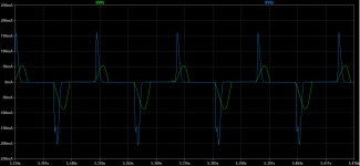
One time in my career I was the power supply guy for a small FF PC. The waveforms you show remind me of the AC line current of the switching PSU in a PC. For export to some countries, we added a PFC (Power Factor Corrector) which was basically an inductor, which did exactly what you show, but for the AC line current. I remember being responsible for company's the internal spec for that part.
Yep that's exactly what it is - passive power factor correction. It also has the advantage of reducing the harmonic content of the rectification pulses by stretching them out, such that whatever DC power supply filtering and amplifier power supply rejection you have is able to reduce it down to an inaudible level.
The disadvantage is that your DC output voltage goes down as you increase the inductance, as the voltage across the choke/inductor is non-zero when the transformer secondary peaks in voltage - the current lags the voltage more and more as a larger inductance is used.
The disadvantage is that your DC output voltage goes down as you increase the inductance, as the voltage across the choke/inductor is non-zero when the transformer secondary peaks in voltage - the current lags the voltage more and more as a larger inductance is used.
Well, I tried another "Russian" single tube "new" ebay 6BQ5 purchase and across 470 Ohms the three remaining tubes of the original quad give me 13.7, 14,2, 14,5 and this new tube 22V. I might as well go back to owning a boat - "satisfaction like standing in a cold shower lighting $100 bills on fire". There was a "25" written on each box of the quad I had previous purchased. I'm not even sure what to ask for, from a potential seller. If I buy a matched pair, I'll probably end up with 22 and 22V...
Listed as "6n18n Vacuum Tube NIB new = 6bq5" 6n18n is what's printed on it also. <$10; I just took the bait, without investigation.
Tonight, I see on-line it curves much differently than a 6P14P, so, my own carelessness. The odd-man tube I intended to replace it with is also a 6P14P, which setup bias more or less on par with the other 3 tubes. So that's why it sets up so differently. Structurally, they appear identical.
Just ordered another "Ness-Tone" branded EL84 / 6BQ5 tube for around $20, shipped, which seller "lesliehammtech" kindly sold to me as a single. Hopefully that one matches up with the other 3 a bit better - another week to find out.
I make more mistakes than Carter has pills. Today, I baked the bread for 3.5 hours, when 45 minutes would do - brought the phone with me so I could hear the alarm sound; never set the timer! Lucky I didnt "bake" the cathode resistor too, with 22V across it.
I think the “mistake” was trying to get off cheap, unfortunately. I don’t think you have a problem that spending ungodly amounts of money - say $100 or more a tube - won’t fix. But that’s what the Big Money Machine wants you to do. At this point I would probably be inclined to just order 8 or 10 “6BQ5 GENERIC” at $20 a pop from my usual source and pick the best 4.
For my experimentation purposes I ordered a batch of 10CW5’s as “alternatives” to EL84. Yeah, I even went off voltage to save a buck a tube. It’s still past rating to run at 400 volts - but nothing new under the sun there. You would need to drop the screen voltage down - way down - to run safely. That might also fix the run away problems you’ve been experiencing with 6BQ5’s.
For my experimentation purposes I ordered a batch of 10CW5’s as “alternatives” to EL84. Yeah, I even went off voltage to save a buck a tube. It’s still past rating to run at 400 volts - but nothing new under the sun there. You would need to drop the screen voltage down - way down - to run safely. That might also fix the run away problems you’ve been experiencing with 6BQ5’s.
- Home
- Amplifiers
- Tubes / Valves
- Various ways to generate NEGATIVE voltages used in Tube Amplifiers