Simply rectifying the existing CT HV winding for negative gets us all the way.That was a very common solution used in 30s & early 40s domestic receivers. It was called back bias
since the negative volts were most often used to bias the output tube, by then usually a pentode.
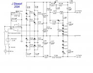
Back bias still works today, here it is in a PP 33 amp, all 2V filamentary tubes.
The bias network is R10, R11, R12 & C3.
This project was published in Glass Audio Projects Book, Summer 2002.
Using this approach I've used this several times to supply tail resisters of two stage
diff amps & the negative bias for the PP output stage, This vers has a slow start mode built in.
Attachments
Back biasing in an audio amplifier in which the pre-stages consume little current compared to the power stage, and with the negative voltage only applied to the control grid(s) of the power stage, is almost a form of cathode bias since the negative voltage depends mostly on the current that the power stage is drawing.
Agree.
For me it IS cathode bias, just with ground taken at a different point upstream, so by definition some part of the string is "negative" (relative to the "new funky ground" that is)..
For me it IS cathode bias, just with ground taken at a different point upstream, so by definition some part of the string is "negative" (relative to the "new funky ground" that is)..
Is it back bias? The key of the approach I showed was to put the smoothing components on the negative rail, and ground the supply after the second choke. 90V is dropped over the last choke (field coil), and a resistance divider delivers -45V to grid of the 2A3.That was a very common solution used in 30s & early 40s domestic receivers. It was called back bias
since the negative volts were most often used to bias the output tube, by then usually a pentode.
...
Most back bias solutions appear to be harvesting negative volts from the ripple before it is smoothed, using a diode.
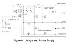
Here is a similar example from a Geloso where the negative bias is extracted from the smoothing for the DC filament supply.
This one uses the negative pulses developed across a 100R resister in the negative return lead of a common CT HV supply.
The resulting pulses are stored in a 1000 microF cap. Then smoothed by 560R & a Zener paralleled with 470 nF.
The resulting pulses are stored in a 1000 microF cap. Then smoothed by 560R & a Zener paralleled with 470 nF.
Attachments

I see now there are different variants of 'back bias'. Some use an AC supply, or one with significant ripple, and a diode to derive a negative supply. The link from JStewart show two variants, using a field coil on the positive or ground, deriving the supply from being elevated from chassis ground.

Rectify the 6.3V and then use a DC-DC step up converter. Just make sure that you get one that is not having common ground, they are only a few dollars on eBait. Suggest you also set up protection in case negative bias fails. (I've got a bunch of them that I bought for making a tube tester that never eventuated, other stuff intervened and now no longer a need for a tube tester.)
Thanks - I got that! So the little circuit I see, like the RCA design mentioned previously, (or some derivative) will do for units having a center tapped secondary.Example: what Marshall does on some of its amps:
and Kodabmx - thanks! I'm probably going to go that route on the amp w/o center tap HV secondary.
Great idea - I never knew such a thing existed. Now, I wonder if they have a PSK-3D-30 model?Interesting that it will take in AC and even DC up to 430 volts. Can't go wrong for $6. Add a 100uH choke and maybe 22uF cap and you should have a pretty clean output.
Bad word choices, right up to saying the opposite of what I wanted to say. I understand cathode bias, done right on all 4 tubes individually, you'll never have to worry... I'd say an illegitimate circuit would be one that does something really undesirable as a side effect, and at the same time that detail isnt all that easy to see.What are ill-legit plans? Endangered electric eels? Mercury batteries?
Thanks, I'll have a look.Do a hunt for "Back Biasing" on the internet.
I cant see where -20V comes from in the schematic. I can see where it goes...The bias network is R10, R11, R12 & C3.
That's interesting; 5W would limit the current to 250 mA, pushing the zener to the edge...You can also use a zener go get a negative rail like Broskie shows here.
Its life hangs on 3 diodes in series...Suggest you also set up protection in case negative bias fails.
Thanks for sharing your design.Simply rectifying the existing CT HV winding for negative gets us all the way.
- Home
- Amplifiers
- Tubes / Valves
- Various ways to generate NEGATIVE voltages used in Tube Amplifiers