Does it "self-balance"?Back biasing in an audio amplifier in which the pre-stages consume little current compared to the power stage, and with the negative voltage only applied to the control grid(s) of the power stage, is almost a form of cathode bias since the negative voltage depends mostly on the current that the power stage is drawing.
Yes, but you could use it with a pass device or just use a 3 pin regulator like LM317/LM337 for it. Hell you could use a string of 30 1N4007 to get about 20V of drop good for an ampere.That's interesting; 5W would limit the current to 250 mA, pushing the zener to the edge...
Yes, it is brilliant - 'cept when the input tubes no longer exist - weren't part of the chassis. So I basically bought a power amp where the cathode current of 4, 6BQ5s has nowhere to go. So, I tied it to ground through a 10R - now where to get some negative voltage? The amp has a nice resistor string / adjustment pot; just need to feed it from a new circuit. Then, the B+ is too high, so as a consequence of doing this, I'd have to do something about, or to compensate for, that.So, this is a vintage amp with the combined 150mA of the four output valves heating the phono input 12AX7s and such? Folks like to rag on this, but I think it's brilliant - highly filtered 150mA of DC wasn't an easy thing before silicon rectifiers. An elegant modern improvement is to add small current sensing resistors, maybe 10R each, into each cathode line, and to leave the rest of the cathode circuit alone, (except maybe install a much, much larger bypass cap. You might even want a Zener across that as safety backup).
Why 10 ohms? That's not preamp heat. 24V@150mA is 160 ohms, which sounds a lot like a cathode bias (which it was). A common Rk for four tubes risks one bad tube screwing up the others, but many-many amplifiers (Fisher, Eico, Marshall) did this without shame or mass customer rejection. Four 640r with four monster cathode caps also works. So does popping in a pair of 12A_7 just as cathode bias.I tied it to ground through a 10R - now where to get some negative
Thinking outside the square one could use photovoltaic optocoupler, they generate a voltage from the light of a LED shining on a small PV array and work like the solar panels on ones roof that are used to generate power. Solar cells are basically current sources up to the max voltage of about 600mV when the PN junction conducts. The IC's have galvanic isolation of 1000s of volts. Some can be configured for 10 volts out at 5uA or 5V out at 10uA. One could use four of these with the outputs connected in series parallel to make a bias supply. Vout could be shunt regulated with a very small zener. The LED forward drop is only 1.4V so a number could be connected in series and still be powered from 6.3V.
https://www.infineon.com/dgdl/Infin...N.pdf?fileId=5546d462602a9dc801607b6ff00c5cca
https://www.infineon.com/cms/en/product/power/solid-state-relay/photovoltaic-isolators/
https://docs.rs-online.com/f367/0900766b808496c0.pdf
Ken K
https://www.infineon.com/dgdl/Infin...N.pdf?fileId=5546d462602a9dc801607b6ff00c5cca
https://www.infineon.com/cms/en/product/power/solid-state-relay/photovoltaic-isolators/
https://docs.rs-online.com/f367/0900766b808496c0.pdf
Ken K
A method I have used in the past is to use a very small mains PCB mountable transformer 250VAC to 24VAC, the 24V winding is connected to the 6.3VAC heater supply, running at such a low flux density the transformer has a very low external B field. The 240VAC winding is rectified to give a low current galvanically isolated supply. This is quite a low parts count solution.
Ken K
Ken K
Oh, 10 was so I could just get a reading on what the total current actually was, while using the -V generator of some sort. I appreciate the suggested values for cathode bias. I think "popping in a pair of 12A_7" is the most creative solution yet! While you may not have the right value and wattage resistors on hand - that's something everyone's got lying around. What are those tubes for? They're bias resistors!Why 10 ohms? That's not preamp heat. 24V@150mA is 160 ohms, which sounds a lot like a cathode bias (which it was). A common Rk for four tubes risks one bad tube screwing up the others, but many-many amplifiers (Fisher, Eico, Marshall) did this without shame or mass customer rejection. Four 640r with four monster cathode caps also works. So does popping in a pair of 12A_7 just as cathode bias.
What kind of driver stage(s) does this mystery amplifier have? Could it be fitted with 150mA heater valves?
All good fortune,
Chris
All good fortune,
Chris
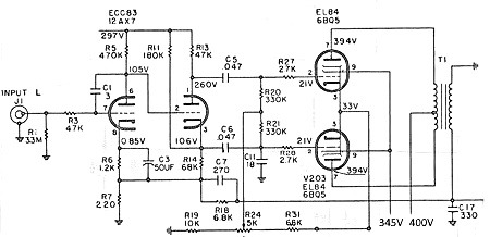
It has a pair of 12AX7s. They're 150 mA as PRR suggested. The phase splitter part's cathode sits 100V above ground; max spec for heater negative to cathode is 200V. Here's what I'm dealing with. I thought I could ground the 6BQ5 cathodes, while providing a negative voltage into R31. Instead, I could drop 24V across the 12AX7 heaters and perhaps adjust R31/R19 to get some range about a (33-21V) nominal?
Attachments

Sure. You'll want a bias voltage of about +24VDC minus 15-ish VDC, so about +9VDC plus/minus maybe 4 or 5 volts.
If I could recommend anything, it would be to include 10R current sensing resistors in each output valve's cathode line. Even if you don't include individual bias trimpots for each valve, you'll at least be able to see how well (or not) balanced each pair is.
Very interesting driver stage. Who designed this?
All good fortune,
Chris
Isn't 33V-21V exactly 12V? Perfect bias for 6BQ5 at original conditions and excellent heat for a 12A_7.a (33-21V) nominal?
It's a Fisher 481A. I paid too much for it, w/o tubes - and taking some significant work to fix. Sounds pretty good though, when I first got it to speak. Now, to make it airtight.Very interesting driver stage. Who designed this?
As you doubtlessly know, modern AC line voltages are the bane of vintage amplifiers. Dedicated Variacs, bucking transformers, or just go commando? Modern (and generally inferior) output valves will have a tough life at over 400VDC.
Since it's a Fisher, it probably has enough B+ filtering to accommodate some reduction in size of the first (input) filter cap. This drops B+ but increases ripple, so it's not a magic bullet. Sounds like this machine might have been modified earlier in its life, so virginity isn't an issue. From a console with separate tuner? The original B+ filter caps were the best available, and may still perform, these many decades later. Coupling caps to the output valve grids should all be replaced though.
I'd be tempted to scrap the fixed/adjustable bias and instead install separate cathode resistors with separate bypass capacitors. Reference the grids to ground, pick a cathode resistor value somewhere around 375 Ohms (each) and a big-enough-that-it-doesn't-matter bypass cap (each), maybe even 1000uF, if they'll fit. The original single bias pot adjustment is without purpose in its current state anyway.
All good fortune,
Chris
As you doubtlessly know, modern AC line voltages are the bane of vintage amplifiers. Dedicated Variacs, bucking transformers, or just go commando? Modern (and generally inferior) output valves will have a tough life at over 400VDC.
There's a trick where you use the extra "floating" 6.3V winding to buck back the AC line winding, which brings down the secondary voltages by some. I dont know if that's legit wrt the insulation between secondaries, but people do it - and sell them to others that way.
I'd need to get the parts to do what you suggest. As it is, I'm pressed to come up with two 9 pin sockets, to even try the heater 12A_7 arrangement - before I butcher out all the 6.3V wiring to the driver tubes - as an experiment first.
What about the idea that the 6BQ5 plate can run at ~400 - as long as the screens are 100V less? Is that a reasonable permanent solution?
You have a spare 6.3VAC winding? You must have lived a really blameless previous life. That's pure gold.
Don't really understand your second paragraph. The earlier thought was to use the existing 12AX7 drivers' heaters as the common cathode resistor for all four output valves. No real need to; hum's not a problem for drivers; so maybe the simpler plan of four separate cathode resistors is overall the best plan. Just a thought. But that's what I'd do in the circumstance.
Audio output valves very often die from G2 overloads, so, yes, that's a reasonable solution. Even in the Golden Age when these guys were built, and valves weren't a niche product from outdated factories, keeping the G2 voltages down was a solid and conservative move. Those guys at Fisher knew some stuff.
All good fortune,
Chris
When you use a dedicated bucking transformer you don’t need to worry about insulation ratings. The whole thing operates at line voltage and doesn’t connect to anything else. When you use a spare winding whats important is the insulation between that one and everything else. The pri:sec isolation will always be good enough if the trafo is competently built, but sec:sec isolation was not designed with that in mind. Insulation might be getting old and brittle on a vintage trafo, and you don’t know how much stress between them was originally intended. With modern Chinese stuff they may not even bother to tape between two 6.3 volt windings. I know on the Anteks they don’t, because its really only intended for 6.3/12.6. A separate rectifier winding would usually be insulated for something way north of B+ and would be fine for bucking the mains, but those are usually 5 volt. If you can get the end bells off, inspect it and SEE a layer of nomex between the winding in question and everything else it’s probably ok. If it’s on the same layer as the other 6.3 I wouldn’t try it.There's a trick where you use the extra "floating" 6.3V winding to buck back the AC line winding, which brings down the secondary voltages by some. I dont know if that's legit wrt the insulation between secondaries, but people do it - and sell them to others that way.
Yes, I've been pretty fortunate that way - and many others. How's it pure gold? For bucking purposes, or for powering something otherwise not possible w/o bolting on another transformer somewhere?You have a spare 6.3VAC winding? You must have lived a really blameless previous life. That's pure gold.
Don't really understand your second paragraph. The earlier thought was to use the existing 12AX7 drivers' heaters as the common cathode resistor for all four output valves. No real need to; hum's not a problem for drivers; so maybe the simpler plan of four separate cathode resistors is overall the best plan. Just a thought. But that's what I'd do in the circumstance.
Audio output valves very often die from G2 overloads, so, yes, that's a reasonable solution. Even in the Golden Age when these guys were built, and valves weren't a niche product from outdated factories, keeping the G2 voltages down was a solid and conservative move. Those guys at Fisher knew some stuff.
All good fortune,
Chris
My second paragraph was basically about "try before you buy". I know all the math adds up, but I like to see - measure - how the circuit sets up with a couple outboard tubes' filaments. Of course - just to make it easier - the 6.3V heater winding hits the driver tubes first, then onto the output tubes. I'd have to tear out and replace all the heater wiring from tranny to output tubes; what if it just doesnt work out for some reason? Then I'd have to put it all back - by then, just think of the shape of my tube socket pins...
I'll look into what it takes to lower those screen voltages. Thanks!
Having worked in the "power supply group" with a first boss who was a former product safety (UL, CSA, TUV) guy, I do have an instinct that this particular "trick" is bad. Also, I'm not about to demo out the power tranny and dissect it to try and figure out if the winding layup would support such a practice. I realize it's a second transformer - another $20-30 into the project - or nothing.When you use a dedicated bucking transformer you don’t need to worry about insulation ratings. The whole thing operates at line voltage and doesn’t connect to anything else. When you use a spare winding whats important is the insulation between that one and everything else. The pri:sec isolation will always be good enough if the trafo is competently built, but sec:sec isolation was not designed with that in mind. Insulation might be getting old and brittle on a vintage trafo, and you don’t know how much stress between them was originally intended. With modern Chinese stuff they may not even bother to tape between two 6.3 volt windings. I know on the Anteks they don’t, because its really only intended for 6.3/12.6. A separate rectifier winding would usually be insulated for something way north of B+ and would be fine for bucking the mains, but those are usually 5 volt. If you can get the end bells off, inspect it and SEE a layer of nomex between the winding in question and everything else it’s probably ok. If it’s on the same layer as the other 6.3 I wouldn’t try it.
Perhaps if I just load the second 6.3V winding with a resistor, that'll have an effect in the right direction. Since it's floating, I could even share some of that load with the other 6.3V winding, spreading magnetic things out a bit across the two windings. As long as I dont turn the PT into an oven...Of course, I have no idea what the ratings are, only that they're probably a bit better than the absolute minimum required. I might get to know how to rate an unknown transformer winding, for its current capability.
“Current capability” is easy to determine - 3.2 amps per square mm. Basically, take the rating per NEC for building wiring and cut it in half. #12 is good for 10 amps in a transformer (20 in the walls if it’s not all coiled up). And wire gauge works like dB, +3 AWG is half the current. If you can’t see the actual wire it does make it a bit more difficult, but sometimes you can get a good look between the layers of paper and nomex.
- Home
- Amplifiers
- Tubes / Valves
- Various ways to generate NEGATIVE voltages used in Tube Amplifiers