lineup said:Nice work HKC
Hi lineup
Thank you.
I will post soldered boards as soon as I finalize. Please keep watching
😉 😉

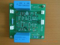
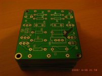
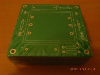
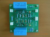
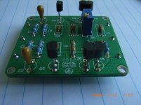
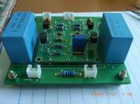
HKC said:More pictures:
I wish my PCB looked like yours, HKC.
But I use a more simple method for my boards (same as Carlos destroyer X often use )
I draw by hand with a water resistant pen onto the copper.
Then I etch in my kitchen with some etch-powder put into water and heated in a kettle on my stove.
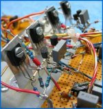
Now, my normal, favourite method is, of course, hard-wire soldering.
Without any boards.
This is theoretically 'best way'. Air insulated circuits are better than anything else.
But not as handy and easy as using a nice PCB.
See my attached picture, for an example.
Regars, Lineup
Attachments
lineup said:
Now, my normal, favourite method is, of course, hard-wire soldering.
Without any boards.
This is theoretically 'best way'. Air insulated circuits are better than anything else.
But not as handy and easy as using a nice PCB.
See my attached picture, for an example.
Regars, Lineup
You are a great joker.
😉
Nice. You do it this way, Pavel.
Best of luck!
As far as my knowledge, Not even TEFLON, dupont whatever, can compeat 100% with proper Air insulation.
Why do we use Air Core inductors for best speaker crossover quality?
Why do we use Air dialectricum Capacitors for best Q = quality?
Here is one old carefully built hardwired =Air Insulation, Microphone Amp of mine.
Fully aluminum shielded and with great performance. Gain x100, +40dB.
Enjoy.
Maybe next time you try this, HKC.
But honestly,
truly in reality, I wouldnt mind much
using such good PCB as on image you have posted, HKC,
of your John Curl amplifier JC-2 variant ...
Lineup - regars
Attachments

Lineup, it is easy to find fault with your approach. Yes, you have removed some DA from the equation, BUT you have added extra lead length of components EXPOSED TO THE AIR, without protection from tarnishing. Not good. Also parts quality must be A-1 and wire quality too, to give you much advantage over a Teflon, or even FR-4 board with these circuits.
Mr. Curl
I use K170/J74 BL class with idss 9.2~9.4ma for my JC-2 clone. What about if I use GR class to replace BL. Would it make any different? Would GR perform better than BL at the input stage?
Best Regards
I use K170/J74 BL class with idss 9.2~9.4ma for my JC-2 clone. What about if I use GR class to replace BL. Would it make any different? Would GR perform better than BL at the input stage?
Best Regards
john curl said:V is best, Bl next, and GR will do in a pinch.
Mr. Curl
Thank you for your answer. With V class K170/J74 the value of the Drain resistors should be changed. I will try 100 Ohm. The value of the Drain resistors on the original schematic.
😀
More like 150 ohms would be best, as the original design was designed for an Id of 15ma to keep the noise to the lowest possible. Toshiba has more Gm and lower Idss, even the V parts, so the load resistor should be proportionally higher. You need at least 1.5V across the load resistors.
Hi Mr. Curl
The information you have given is very interesting to me. It is no doubt that I will try to locate some V class K170/J74 to replace the BL.
I set the bias current of the output transistors 2N4401/4403 @ 50ma with +/- 15v voltage therefore the power consumption of each transistor is 700mw which is 75mw exceed than the original power dissipation 625mw of these transistors.
These transistors are now running very hot so I think heat sinks must be added to help dissipate the heat otherwise they could be damaged.
700mW through a 625mW (fairchild) device sounds like they are already damaged.
Try 20mA to 25mA of bias.
Even with a good heatsink around both the curved surface and the flat surface with adequate heatsink compound, you will be right at the 1.5W (Tc<=25degC, Rth-jc=83.3C/W) limit pushing 700mW through these devices.
Try 20mA to 25mA of bias.
Even with a good heatsink around both the curved surface and the flat surface with adequate heatsink compound, you will be right at the 1.5W (Tc<=25degC, Rth-jc=83.3C/W) limit pushing 700mW through these devices.
I have downloaded OnSemi datasheet for 2N4401/2N4403.
2N4401 is TO-92.
Even if max power rating can be higher than normal 500 mW,
I would never run a TO-92 plastic above like 400 mW.
Transistors simply will not work best when getting hot.
Reduce your current.
Like 25 mA would be my max for 15 Volt.
The rule is,
to not use too much more current than you need
for good operation into your loads.
I do not know what output stage power was used in original JC-2.
But I can not imagine Curl used TO-92 packages at 625 mW.
But he will tell me, if I am wrong 😉
😎 Very nice work with your PCB, HKC.
I love this image:
http://www.diyaudio.com/forums/attachment.php?s=&postid=1565080&stamp=1216429984
Regards Lineup
- Home
- Source & Line
- Analog Line Level
- Variation on the JC-2 preamplifier