The current mirrors gives you double the drive current for the miller compensation capacitance, so the slew rate of the VAS doubles. You also get more LTP gain.
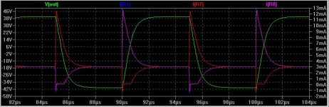
A sim of the The H-bridge currents attached below. The green trace is the VAS output, driven to 40V peak with a fast rise time 100kHz square wave input.
Purple and red traces are the currents in each half of the H-bridge.
As can be seen, the standing current is 3mA per leg (equivalent to a 6mA tail current). With such a relatively high "tail" current and 100 ohm H-bridge resistors used for emitter degeneration, linearity isn't compromised.
Under these drive conditions the "on demand" current deliverable by each LTP to charge each miller cap peaks at 13mA.
Attachments
Well what do you actually think of Tom Colangelo as designer?
Interestingly, while he is mentioned now and then, nobody says a word or two about his engineering abilities/designs; also the thread about his Cello Encore (including the schematic) was quite silent. I am not sure why this is so, the design itself is unusual and interesting.
Why so?
All the best, Hannes
Cello Encore schematics (2 pages)
discussion on DIYAudio (starts after a couple of postings)
h_a said:
Interesting. This design reminds me of Bob's front end, from his 1984 JAES "error correction" paper.
syn08 said:
Interesting. This design reminds me of Bob's front end, from his 1984 JAES "error correction" paper.
As drawn the loading scheme for the second LTP (D11, Q7, Q8, Q10) doesn't make a lot of sense.
😕
G.Kleinschmidt said:
As drawn the loading scheme for the second LTP (D11, Q7, Q8, Q10) doesn't make a lot of sense.
😕
No it doesn't, there's most likely an error in the schematic. Q7 should probably be between Q6 and Q8.
Yes this is a mistake in the schematic, the dot on the emitter of Q7 and on the collector of Q8 is missing; Q8/Q10 is a current mirror, Q7 a variation on a cascode.
Note the use of C33 to sort-of bootstrap (for high frequencies) the VAs loading resistors R58, R59.
The biasing of the outputstage is still not understood, so if somebody wants to enlighten me (or others interested in the Cello), it would be greatly appreciated!
Also transistor substitutions seem to greatly affect stability?
All the best, Hannes
@syn08: Yes you're right! What a magnificent memory! I just had a look (after a long time) and the frontends have similarities (bipolar cascoded jfets differential connected via predrivers to balanced VAS; lead-lag/lag compensated, differential stabilized via R10/C5) - not a bad relationship, since Bob's frontend slews at 300V/mus...
All the best, Hannes
All the best, Hannes
G.Kleinschmidt said:
Like this (front end designed for my monster class A amp)?
That's along the same lines. I was thinking of a resistor crossing the "H" too. There are some magic values that give a flat transfer function that we use in some op-amp inputs. Along the same lines as the magic output ballast resistors. I once had a copy Pedersons original hand written derivation. FET's don't have the same cancellation, but you can create a pretty wide linear region.
That Cello circuit might have some twists but in general it looks like another op-amp on steroids. The little 1pF here 5pF there compensation networks to me mean that thing is very layout and component sensitive.
janneman said:
Didn't Dick Burwen do a lot of designing for him as well?
Jan Didden
🤐
I thought Dick was sort of a "if one op-amp is good 5 is better kind of guy". His DNR circuit had like 10 op-amps in every signal path. These were vintage 70's op-amps too. MHO of course.
Opamp on steroids? Would you please elaborate? I have no special associations to that word - maybe highly integrated ICs with crazy gain, but that won't fit here ;-) Oh and global neg. feedback, which does not fit here as well, since there's simply no feedback from the output back (remember the outputstage is on page 2, easily overlooked).
Agreed!
However I try my luck by avoiding a groundplane and generally trying to avoid parasitics in the layout and I think that will fit.
All the best, Hannes
EDIT: spelling...stereoids 😀
The little 1pF here 5pF there compensation networks to me mean that thing is very layout and component sensitive.
Agreed!
However I try my luck by avoiding a groundplane and generally trying to avoid parasitics in the layout and I think that will fit.
All the best, Hannes
EDIT: spelling...stereoids 😀
a discrete opamp with adequate current output into lower impedance loads.h_a said:Opamp on steroids? Would you please elaborate?
Thanks for the steroids, but what means opamp in this context?
Please excuse my ignorance, I'm not particularly adept with opamps!
Have fun, Hannes
Please excuse my ignorance, I'm not particularly adept with opamps!
Have fun, Hannes
scott wurcer said:
🤐
I thought Dick was sort of a "if one op-amp is good 5 is better kind of guy". His DNR circuit had like 10 op-amps in every signal path. These were vintage 70's op-amps too. MHO of course.
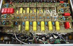
I had the chance to open up a Cello Palette with its umpteen little pcb's, with the standoffs used for power and signal transmission. I was told that it was designed by Dick.
Jan Didden
http://en.wikipedia.org/wiki/Op-amph_a said:but what means opamp in this context?
used as an analogue operator to multiply/divide/integrate/differentiate/add/subtract etc.
In this case it's a voltage multiplier and impedance converter (current multiplier).
I'm sorry to completely sidetrack now, but hey, that's exactly what every amp does. Besides the power buffer without gain, that one does only impedance conversion.
So I guess it does not mean anything special.
Thank you, Andrew! Hannes
So I guess it does not mean anything special.
Thank you, Andrew! Hannes
h_a said:Thanks for the steroids, but what means opamp in this context?
Please excuse my ignorance, I'm not particularly adept with opamps!
Have fun, Hannes
Sorry if my joke is not understood. I meant diff-input, VAS, output buffer, sort of the same parts as a bi-FET op-amp, just this one puts out amps and lots of volts. No intention of knocking this design path.
h_a said:@syn08: Yes you're right! I just had a look (after a long time) and the frontends have similarities (bipolar cascoded jfets differential connected via predrivers to balanced VAS; lead-lag/lag compensated, differential stabilized via R10/C5) - not a bad relationship, since Bob's frontend slews at 300V/mus...
I wonder which amp took precedence?

Thanks Scott, for accurately denoting what kind of designs Tom Colangelo made. Super op amps.
His most radical departure from my designs can be seen initially in the ML-3 Power Amp. Low slew rate, very complex, design. That was his pattern, sort of: If 2-3 parts did a pretty good job, let's use 10-20 parts and get better specs, if possible.
Dick Burwen is a brilliant engineer, but he is OP AMP happy, just like Scott implied.
I replaced his IC based modules in 1974, with discrete designs that sounded better (if that is actually possible, of course). When I left the scene, and Mark lost Levinson, the company, he hired Dick Burwen again to make the famous Cello EQ, which is suspect is one of the best in the world. I certainly would like to have one.
Tom C. followed Mark to Cello, and remained with him over the years, until Cello fell, at least. I am sure that Tom was easier to work with than me, although I only met him a few times, and he was listed as a tech when Mark and I went our separate ways.
- Home
- Source & Line
- Analog Line Level
- Variation on the JC-2 preamplifier