The original parts usually had an Idss between 15 and 30ma. That is why we needed a pot to adjust them to some nominal current. They also had between 4 and 5 times less transconductance, so they needed to be turned down a bit, so they would not exceed their Idss by very much at peak drive levels. Toshiba fets are different, and your parts can be operated at 6-8ma without much problem, because it is difficult to forward bias them, as they will add 4ma or more for every .1V overdrive, and you can do .2-.3V overdrive without too much trouble with a reasonably low z source, below 100K ohm. Microphone electronics are different, and you should never overbias the input fet on a microphone, because the additional leakage will upset the bias conditions. I work my mikes up to 10,000,000,000 ohms or even more, if necessary.
HKC said:Mr. Curl
What was the idss of the input JFets on the ling stage you used on the original JC-2 circuit? I am now using JFets K170/BL & J74BL with idss 9.2~9.4ma and adjusted the Drain resistors from 100 Ohm to 150 Ohm and the Emitter resistors from 20 Ohm to 22 Ohm.
I am trying to do my JC-2 clone as close as possible to your original design.
🙂
This is what's in the modules:
http://www.audioasylum.com/audio/tweaks/messages/3/35469.html
Those were the ML-1 modules. I do not necessarily approve of the ML-1 modules. They were modified by Tom Colangelo, after he took over.
john curl said:Those were the ML-1 modules. I do not necessarily approve of the ML-1 modules. They were modified by Tom Colangelo, after he took over.
John, you should be flattered that people still find your 30+ year old circuits useful. If I knew I was only driving 1 meter of interconnect and a 50k volume control I don't think a lower current TO-92 version with common parts is all that far fetched. That's what DIY is all about. For light loads I still don't see the FET's enhancing, even a little.
I talked to Dick, nothing but good things were said about everyone. I'm glad he's well and can still work every day. Unfortunately he said that if I blow his little speakers he can't get me drivers anymore.
Scott, I like class A, you like class B. That is why I had to modifiy your AD797 with an external current source. Read Gedlee, and note what I am concerned with.
Some people think that higher order distortion is OK, if it is reduced with lots of negative feedback. I found it better to use reduced feedback and higher Iq.
By the way, did Dick give you any hint as to how he operates your AD797 in his phono stage?
For the record:
The ML-1 op amp module looks like a hybrid version of what I designed for Mark Levinson to replace the IC based Burwen modules in the LMP-2, and the LNC-2 electronic crossover in 1975. The only real difference was the use of bipolar transistors in the output, rather than complementary j-fets. This kind of circuit, being an op amp, rather than a transconductance amp, has more gain and therefore more negative feedback is possible. This lowers the measured distortion below the original JC-2 modules, as the feedback hides the distortion.
Also, the original JC-2 line modules were originally designed for the Grateful Dead and without any technical assistance from Mark Levinson or his associates, and could be loaded with a 600 load. Mark repackaged the parts in a nice modular package with thermal epoxy for the Grateful Dead as a subcontractor. Later we adapted this design for the JC-2, and we reduced the operating current slightly, BUT we still used thermal epoxy around the subsequent TO-92 devices to keep the current relatively high, compared to an IC, for example. Please remember, we were REPLACING the best IC's available at the time with these modules. The marketplace acceptance showed us that we were on the right track. Now, completely global loop feedback free modules are best, and this is what I am doing for my BEST designs today and for the last decade. Of course, my Parasound designs have negative feedback, BUT I don't starve any stage just to save heatsink material, and be [up to date] so to speak.
Just a question, and if it's out of line, I apologize, but: I met ML some 20 years ago and had an interview with him in the margins of a Cello demo evening.
The talk left me kind of puzzled: is ML an engineer?
Jan Didden
The talk left me kind of puzzled: is ML an engineer?
Jan Didden
john curl said:Scott, I like class A, you like class B. That is why I had to modifiy your AD797 with an external current source. Read Gedlee, and note what I am concerned with.
Some people think that higher order distortion is OK, if it is reduced with lots of negative feedback. I found it better to use reduced feedback and higher Iq.
Did you (or anyone else) ever think of trying current mirrors, like in that circuit of post no1? With an "H" of resistors between the FET's you can independently control the bias and transconductance. In fact you can then tune the circuit for a whole range of GNF to almost none. It's very robust, into the 6k I can't get the distortion over -100dB for any reasonable setting.
I can't use listening tests, I once accidentally disconnected one tweeter on my two way speakers and didn't notice it for a month. I also transcribed an LP for a friend with a prototype preamp that was oscillating at 60MHz. We all thought the results were stunning including the recording engineer that was working on the CD re-release.
Maybe OT and if so I am sorry but has anyone tried MOSFET's instead of bipolar in the output? I have seen the Borbely Audio preamp that is similar with JFET's (posted earlier) but I was thinking more like ZVP3306/ZVN3306. Just a thought that may or may not work, I guess I will just have to try it sometime. I am going to build a JC-2 but what can I use for the N/P-Channel JFET's that aren't Toshiba's? I can find lots of N-Channels, but complimentary P-Channels seem to be harder to get. I need them for a slated JC-3 and a Aleph J too🙁 , I guess I might just have to order up some Toshiba's. Just thought I would ask about the MOSFET's. Back to life for me.
JLH 1969+Ani DiFranco/Dave Matthews+Grilling tuna steaks+New Belgium 1554 Ale+Putting off my essay(college student)+52 degrees and sunny=A great Wednesday afternoon in Iowa. 🙂
Cheers
James
JLH 1969+Ani DiFranco/Dave Matthews+Grilling tuna steaks+New Belgium 1554 Ale+Putting off my essay(college student)+52 degrees and sunny=A great Wednesday afternoon in Iowa. 🙂
Cheers
James
ML is not an engineer. That is what got me into trouble. In 1975, I insisted that he hire at least one engineer so that my phone bills from Switzerland (where I lived at the time) would be significantly reduced. Then I could talk 'engineer' to the engineer and he could translate it into more conventional language for Mark Levinson. However, once the first engineer (George Mayhew sp. ) was hired, I was considered expendable. You know, they know everything that I have done, and they can 'improve' it from there. Sound familiar? Tom Colagelo apparently pushed George out and became ML's right hand man. Then, I did not get credit for the JC-2, so I threatened to sue and it became the ML-1, and the JC-3 became the ML-2.
JPeitzman said:
...has anyone tried MOSFET's instead of bipolar in the output?
Oi! All right, already! I'll post the flippin' circuit! Jeez...
Probably late tonight or sometime tomorrow. I've got the rewrite the confusticated intro to reflect recent events.
Yes, it's a bloody amplifier, but if you disconnect the front end and use it stand-alone, it'll make a dandy preamp. The way it's biased it'll drive most anything on the planet. Jump start your car with it for all I care.
Grey
Sorry Grey, no rush, I am just curious and now excited. I thought I saw mention of something like FET outputs from you but I couldn't remember. Thought I was onto something but sorry, didn't mean to stir the pot.
Saw a schematic a little bit back too with ZVN/ZVP's in the input instead of the JFET, that caught my attention too. I can't for the life of me remember who posted it, I have a very poor memory. Plus I am a bit frazzled and out of it right now due to my essay I am writing, can't concentrate on anything.
Again take your time Grey, no rush, at least from me.
Cheers
James
PS: Since it is a "bloody amplifier" is it by chance a FET output JC-3?
scott wurcer said:
Did you (or anyone else) ever think of trying current mirrors, like in that circuit of post no1? With an "H" of resistors between the FET's you can independently control the bias and transconductance.
john curl said:
Chas Hansen uses mirrors. I tend to avoid them on input stages.
Charles has been after me to try current mirrors. I have not yet done so as my current PCB artwork will not readily support such a thing. Yes, I will get to it at some point, but I've got to work out how I want to go at it, then make the boards--I've long since passed the point where I can cobble things together on a push board.
I may be wrong, but I believe Nelson has said that he also used current mirrors in at least one iteration of his X front end.
John,
Could you elaborate as to why you don't feel current mirrors are appropriate for front ends? Is it noise?
Grey
"believe Nelson has said that he also used current mirrors in at least one iteration of his X front end." You wouldn't happen to be talking about the UGS and the new X's would you? Such a sexy design.
john curl said:The original parts usually had an Idss between 15 and 30ma. That is why we needed a pot to adjust them to some nominal current. They also had between 4 and 5 times less transconductance, so they needed to be turned down a bit, so they would not exceed their Idss by very much at peak drive levels. Toshiba fets are different, and your parts can be operated at 6-8ma without much problem, because it is difficult to forward bias them, as they will add 4ma or more for every .1V overdrive, and you can do .2-.3V overdrive without too much trouble with a reasonably low z source, below 100K ohm. Microphone electronics are different, and you should never overbias the input fet on a microphone, because the additional leakage will upset the bias conditions. I work my mikes up to 10,000,000,000 ohms or even more, if necessary.
Hi Mr. Curl
Thank you again for your reply. The information is very helpful.
Look at the J310 and J271. While not, strictly speaking, complements, they are high current JFETs. In most respects the Toshibas are superior, though.
Grey
Grey
john curl said:ML is not an engineer. That is what got me into trouble. In 1975, I insisted that he hire at least one engineer so that my phone bills from Switzerland (where I lived at the time) would be significantly reduced. Then I could talk 'engineer' to the engineer and he could translate it into more conventional language for Mark Levinson. However, once the first engineer (George Mayhew sp. ) was hired, I was considered expendable. You know, they know everything that I have done, and they can 'improve' it from there. Sound familiar? Tom Colagelo apparently pushed George out and became ML's right hand man. Then, I did not get credit for the JC-2, so I threatened to sue and it became the ML-1, and the JC-3 became the ML-2.
Thanks John, you confirmed my suspicion. Didn't Dick Burwen do a lot of designing for him as well? I thought the Cello line was showing Dicks handiwork.
Jan Didden
scott wurcer said:
Actually the circuit in post #1 is sort of a FET version of the "current on demand" input stage like a bipolar "H-bridge" input. The concept of slew rate gets a little fuzzy, we make 'em with inputs running at 100uA that still slew at 3000V/us. You can tilt the input and get >Idss out with almost any value for the R. BTW the Hafler style complimentary circuits (long-tailed pairs with current sources to the rails) are not current on demand and have a slew rate in the classic sense.
scott wurcer said:Did you (or anyone else) ever think of trying current mirrors, like in that circuit of post no1? With an "H" of resistors between the FET's you can independently control the bias and transconductance. In fact you can then tune the circuit for a whole range of GNF to almost none. It's very robust, into the 6k I can't get the distortion over -100dB for any reasonable setting.
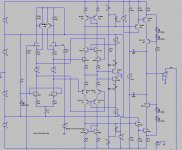
Like this (front end designed for my monster class A amp)?
Attachments
- Home
- Source & Line
- Analog Line Level
- Variation on the JC-2 preamplifier